Electrophoretic display elements

a technology of display elements and display elements, applied in the direction of static indicating devices, non-linear optics, instruments, etc., can solve the problems of inadequate service life of these displays, preventing their widespread use, and gas-based electrophoretic media being susceptible to the same types of problems

Inactive Publication Date: 2006-09-14
E INK CORPORATION
View PDF5 Cites 189 Cited by
  • Summary
  • Abstract
  • Description
  • Claims
  • Application Information

AI Technical Summary

Benefits of technology

[0039] This method of the present invention may hereinafter for conven

Problems solved by technology

Nevertheless, problems with the long-term image quality of these displays have prevented their widespread usage.
For example, particles that make up electrophoretic displays tend to settle, resulting in inadequate service-life for these displays.
Such gas-based electrophoretic media appear to be susceptible to the same types of problems due to particle settling as liquid-based electrophoretic media, when the media are used in an orientation which permits such settling, for example in a

Method used


Image

  • Electrophoretic display elements
  • Electrophoretic display elements
  • Electrophoretic display elements

Examples


Embodiment Construction

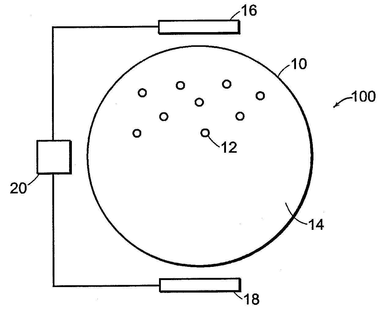
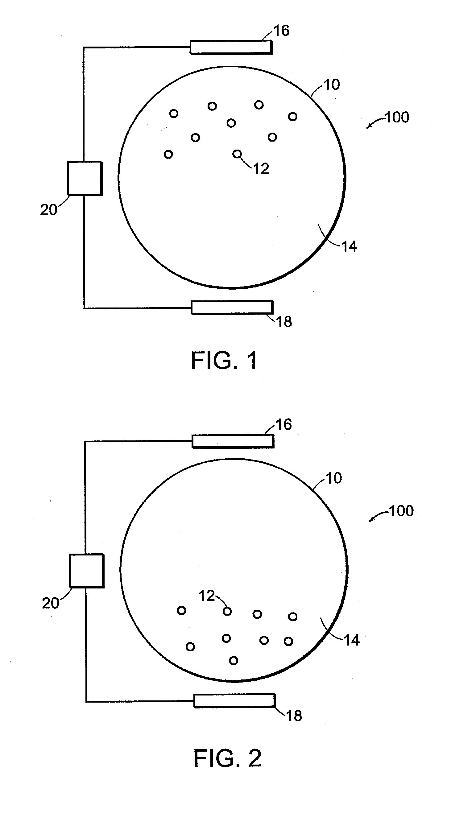
[0095] The present invention relates to methods and materials for an electrophoretic display such that the particle motion is a substantially controlled, non-linear function of the applied electric field. The present invention also relates to methods and materials for controlling color intensity in an electrophoretic display element. More particularly, in one aspect, the techniques and materials of the invention prevent, or at least significantly impede, the motion of charged pigment particles in the display under one set of conditions, while allowing them to move relatively freely under a second set of conditions. The invention may enable, for example, passive addressing of the display and can eliminate gravitational or diffusional motion of the pigment particles over time, thus enhancing the bistable nature of the display.

[0096] As set forth above, the present invention has three principal aspects, namely three color electrophoretic display elements, sticky particles display elem...


PUM


Abstract

The invention relates to methods and materials for controlling stability and color intensity in an electrophoretic display element. Filler particles in the electrophoretic display element, serves as a medium that the electrophoretic particles must travel through during switching between optical states of the display. The filler particles provide improved control over the color intensity of the electrophoretic display element. In addition, the filler particles create resistance to the migration of the electrophoretic particles, thereby improving the bistability of the electrophoretic displays and inhibiting settling of the electrophoretic particles. Also, migration resistance provided by the filler particles can enable threshold addressing of an electrophoretic display.

Description

REFERENCE TO RELATED APPLICATIONS [0001] The present application is a continuation-in-part of application Ser. No. 10 / 298,468, filed Nov. 18, 2002 (Publication No. 2003 / 0132908), which in turn is a continuation-in-part of application Ser. No. 09 / 564,125, filed May 3, 2000 (now U.S. Pat. No. 6,693,620), which claims benefit of U.S. Provisional Application Ser. No. 60 / 132,303, filed May 3, 1999. The entire disclosures of the aforementioned applications, and of all other U.S. patents, and published and copending applications referred to below are also herein incorporated by reference.BACKGROUND OF INVENTION [0002] This invention relates to electrophoretic display elements and electrophoretic displays containing such elements. More specifically, this invention relates to electrophoretic display elements in which the electrophoretic mobility of the electrophoretic particles and / or the switching behavior of the particles varies with the applied field, and to electrophoretic display elemen...

Claims


Application Information

Patent Timeline
IPC IPC(8): G09G3/34G02F1/167G02F1/16757G02F1/1685
CPCG02F1/167G02F2001/1678G09G3/344G09G2310/06G02F1/16757G02F1/1685
Inventor DANNER, GUY M.AMUNDSON, KARL R.HERB, CRAIGZHANG, LIBING
Owner E INK CORPORATION
Why Eureka
Try Eureka