Dental implant system

Inactive Publication Date: 2006-09-14
HURSON STEVE
View PDF99 Cites 23 Cited by
  • Summary
  • Abstract
  • Description
  • Claims
  • Application Information

AI Technical Summary

Problems solved by technology

This bone loss is undesirable both aesthetically and structurally.

Method used


Image

  • Dental implant system
  • Dental implant system
  • Dental implant system

Examples


Embodiment Construction

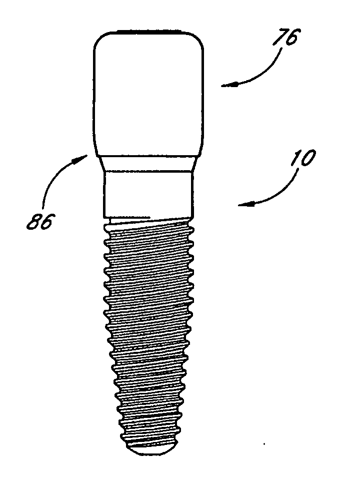
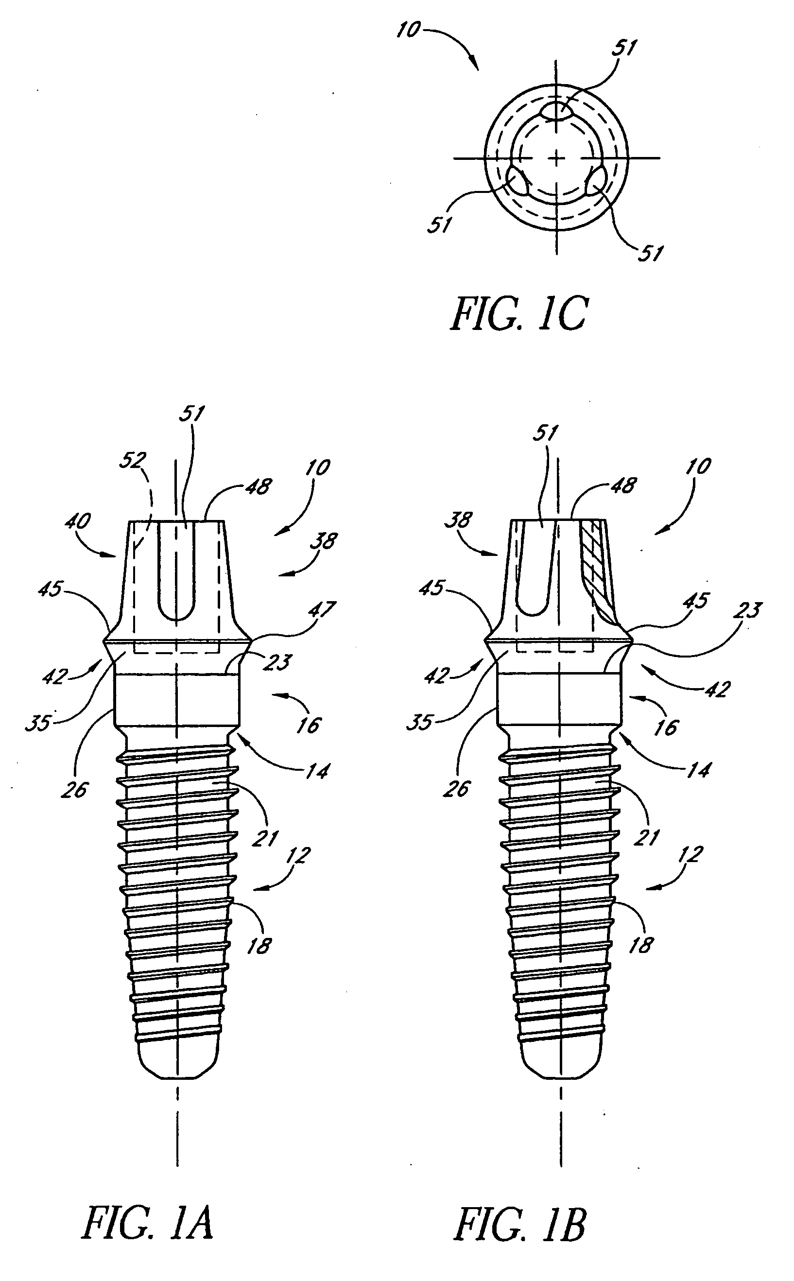
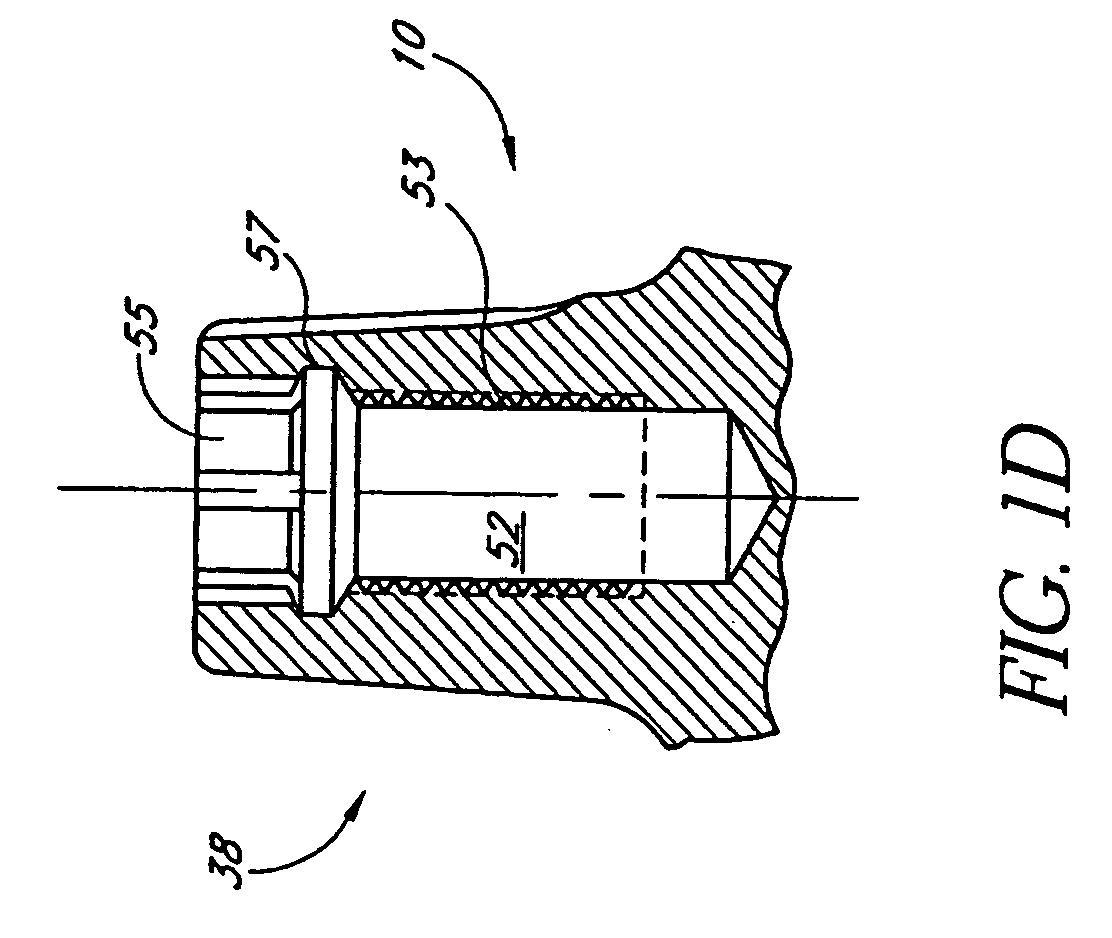
[0042]FIGS. 1A-1C illustrate an exemplary embodiment of single stage dental implant 10. As is known in the art, with a single stage implant, stage I and stage II surgery may be combined into a single procedure. The implant 10 is preferably sized and dimensioned to receive and support one or more dental attachments or components, which will be described in detail below. In particular, the dental implant 10 is sized and dimensioned to support a final restoration. The implant 10 is preferably made of a dental grade titanium alloy, although other suitable materials may also be used.

[0043] As best seen in FIG. 1A, the implant 10 includes a body portion 12, a neck 14, and a collar 16. The body portion 12 is preferably generally cylindrical with a tapered distal end and includes threads 18 that may be configured to mate with a preformed threaded hole or osteotomy formed in the patient's jawbone (not shown). However, it should be appreciated that the body portion 12 may also be configured ...


PUM


Abstract

A dental implant and abutment combination includes an implant body portion and an abutment portion. The implant body portion is located at a distal end of the combination and is configured to lie at least partially below a crest of a patient's jawbone. The abutment portion is located at a proximate end of the combination and is configured to lie at least partially above the crest of the patient's jawbone. The abutment portion comprises a flared portion, a shoulder portion and a final restoration portion. The shoulder portion lies between the flared portion and the final restoration portion.

Description

PRIORITY INFORMATION [0001] This application is a continuation of U.S. patent application Ser. No. 10 / 748,869, filed Dec. 30, 2003, which claims the priority benefit under 35 U.S.C. § 119(e) of Provisional Application 60 / 438,266 filed Jan. 3, 2003, the entire contents of these applications are hereby incorporated by reference herein.BACKGROUND OF THE INVENTION [0002] 1. Field of the Invention [0003] The present invention relates generally to dental implants and more particularly to dental implants systems. [0004] 2. Description of the Related Art [0005] Implant dentistry involves the restoration of one or more teeth in a patient's mouth using artificial components. Such artificial components typically include a dental implant and a prosthetic tooth and / or a final abutment that is secured to the dental implant. The process for restoring a tooth may be carried out in three stages. [0006] Stage I involves implanting the dental implant into the bone of a patient's jaw. The oral surgeon ...

Claims


Application Information

Patent Timeline
IPC IPC(8): A61C8/00
CPCA61C8/0001A61C8/0022A61C8/0075A61C8/0077A61C8/0078A61C8/008
Inventor HURSON, STEVE
Owner HURSON STEVE
Why Eureka
Try Eureka