
Intravascular filter assembly

a filter and vascular technology, applied in the field of embolism protection, can solve the problems of pulmonary embolism that can often be fatal, blockage of pulmonary arteries, and patients are constantly at risk of a clot breaking free,

Inactive Publication Date: 2006-09-14
BOSTON SCI SCIMED INC
View PDF37 Cites 96 Cited by
  • Summary
  • Abstract
  • Description
  • Claims
  • Application Information

AI Technical Summary

Benefits of technology

[0015] The above summary of some embodiments is not intended to describe each disclosed embodiment or every implementation

Problems solved by technology

These patients are constantly at risk of a clot breaking free and traveling via the inferior vena cava to the heart and lungs.
Pulmonary embolization can frequently be fatal, for example when a large blood clot interferes with the life-sustaining pumping action of the heart.
If a blood clot passes through the heart it will be pumped into the lungs and may cause a blockage in the pulmonary arteries.
A blockage of this type in the lungs will interfere with the oxygenation of the blood causing shock or death.
It is recognized in the art that it is undesirable for a thrombus filter to change position once it has been place in the desired position by a physician.
If a filter becomes loose in the lumen of a blood vessel, it may migrate to a position where it may be ineffective at capturing thrombi.
Alternately, and more seriously, a loose thrombus filter may migrate to a dangerous or life threatening position.
Removing the filter once the anchor portions have been encapsulated may result in trauma to the vessel wall.

Method used


Image

  • Intravascular filter assembly
  • Intravascular filter assembly
  • Intravascular filter assembly

Examples


Embodiment Construction

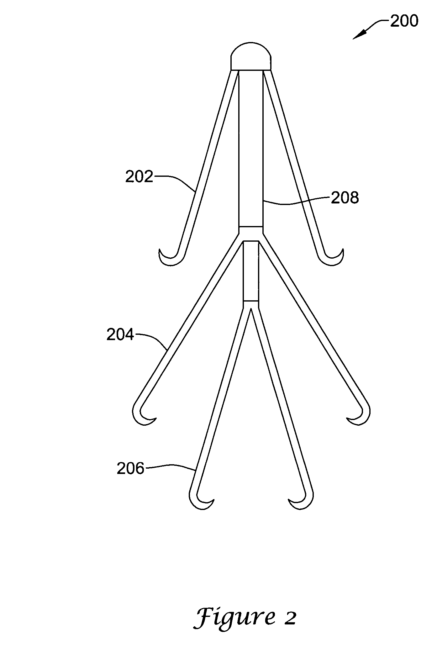
[0027] The following description should be read with reference to the drawings, in which like elements in different drawings are numbered in like fashion. The drawings, which are not necessarily to scale, depict selected embodiments and are not intended to limit the scope of the invention. Although examples of construction, dimensions, and materials are illustrated for the various elements, those skilled in the art will recognize that many of the examples provided have suitable alternatives that may be utilized.

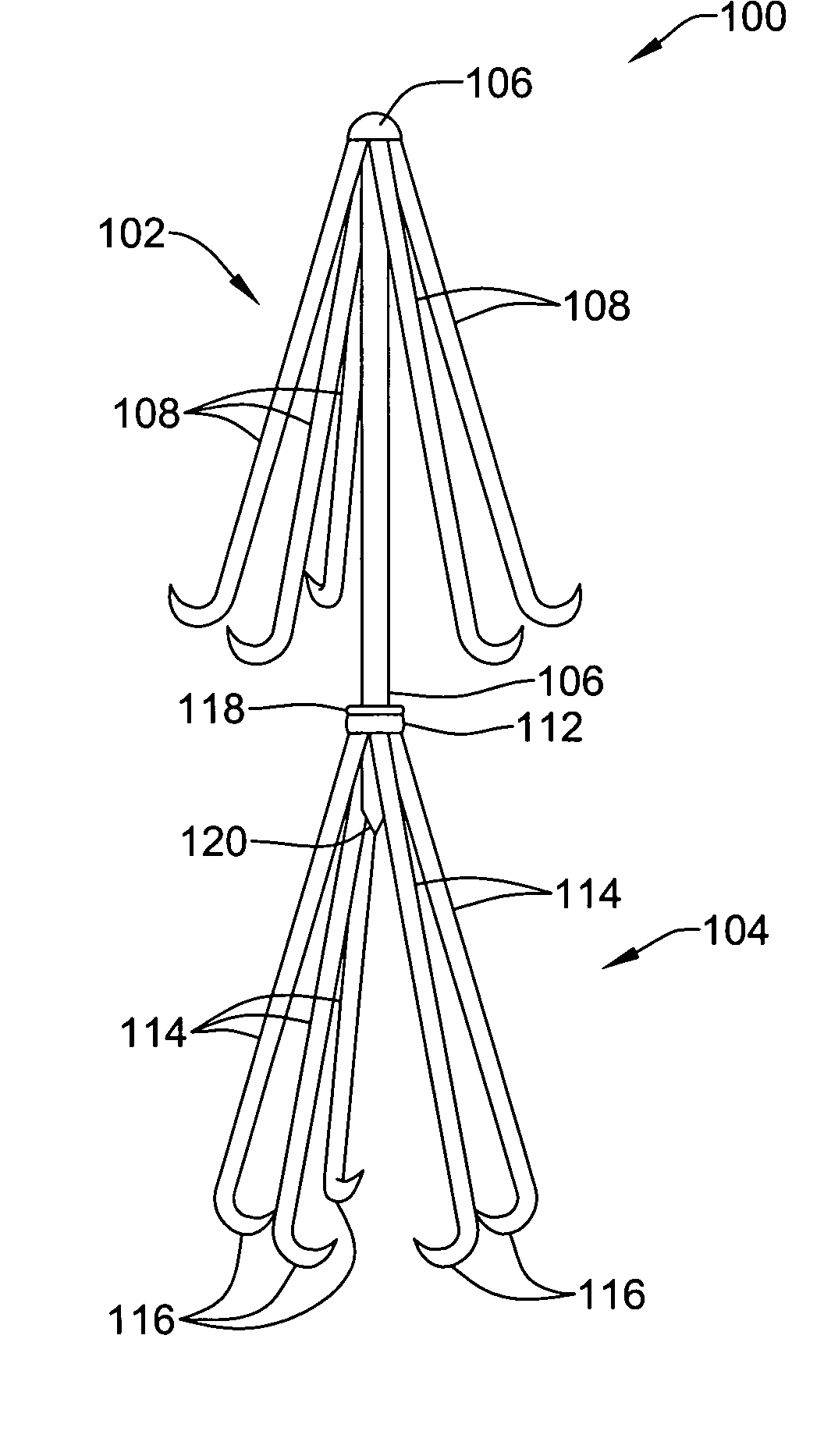
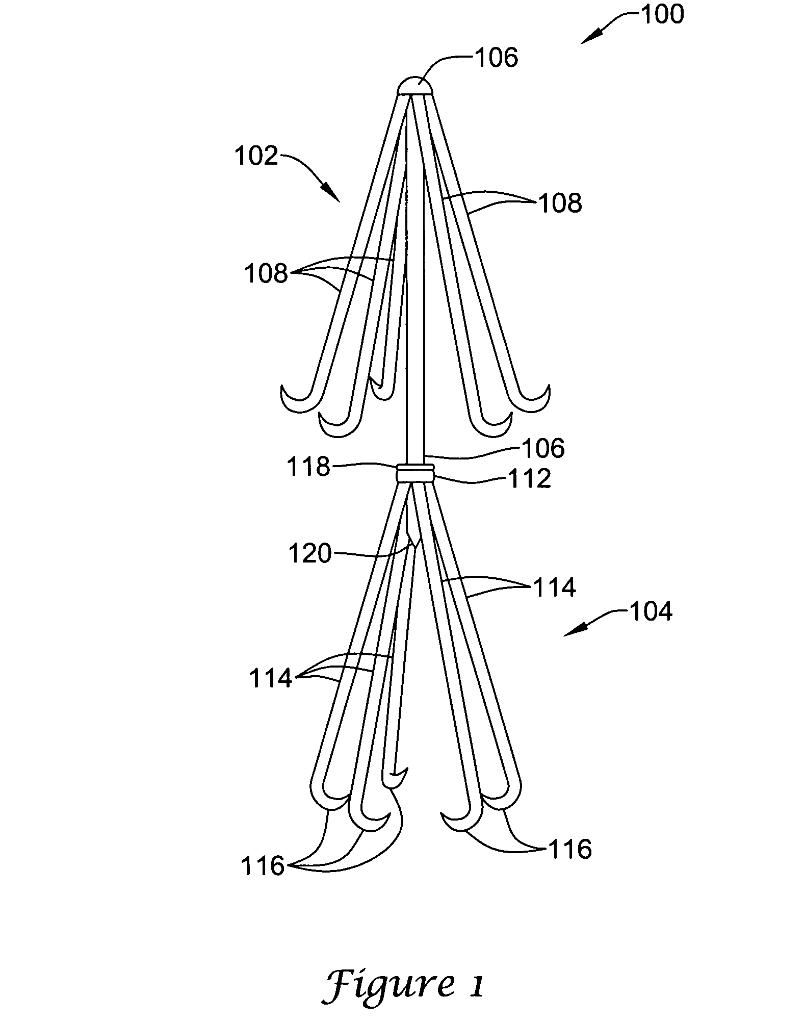
[0028]FIG. 1 is a perspective view of an intracorporal filter assembly 100. Assembly 100, like other assemblies of the illustrative embodiments, is depicted as an intravascular filter though the invention is suitable for use in intracorporal filters besides intravascular filters. Assembly 100 includes a first filter 102 and a second filter 104. Filters 102 and 104 are removably connected by an elongate member 106. Filters 102 and 104 are depicted as Greenfield style filters....


PUM


Abstract

An intravascular filter assembly for use in a body vessel lumen having a wall, which may include a first filter having a mouth facing in a first direction at a first location for receiving emboli and an end in a second direction opposite the first direction, and a second filter having a mouth facing in the first direction at a first location for receiving emboli and an end in the second direction, wherein the second filter is removably attached to the first filter.

Description

FIELD OF THE INVENTION [0001] The present invention pertains to embolic protection. More particularly, the present invention pertains to embolic protection filters and methods of making the same. BACKGROUND OF THE INVENTION [0002] There are a number of situations in the practice of medicine when it becomes desirable for a physician to place a filter in the vascular system of a patient. One of the most common applications for vascular filters is the treatment of Deep Venous Thrombosis (DVT). Deep Venous Thrombosis patients experience clotting of blood in the large veins of the lower portions of the body. These patients are constantly at risk of a clot breaking free and traveling via the inferior vena cava to the heart and lungs. This process is known as pulmonary embolization. Pulmonary embolization can frequently be fatal, for example when a large blood clot interferes with the life-sustaining pumping action of the heart. If a blood clot passes through the heart it will be pumped in...

Claims


Application Information

Patent Timeline
IPC IPC(8): A61M29/00A61F2/06
CPCA61F2/01A61F2002/011A61F2002/016A61F2230/005A61F2230/0067A61F2230/0093A61F2/011A61F2/0105A61F2/012
Inventor EIDENSCHINK, TRACEE E.J.
Owner BOSTON SCI SCIMED INC
Learn More