

Planer board lighting device
a technology of lighting apparatus and planer board, which is applied in the field of fishing devices for planer board, can solve the problem that the apparatus has not been available to anglers
- Summary
- Abstract
- Description
- Claims
- Application Information
AI Technical Summary
Benefits of technology
Problems solved by technology
Method used
Image

Examples
Embodiment Construction
[0023] Detailed descriptions of the preferred embodiment are provided herein. It is to be understood, however, that the present invention may be embodied in various forms. Therefore, specific details disclosed herein are not to be interpreted as limiting, but rather as a basis for the claims and as a representative basis for teaching one skilled in the art to employ the present invention in virtually any appropriately detailed system, structure or manner.
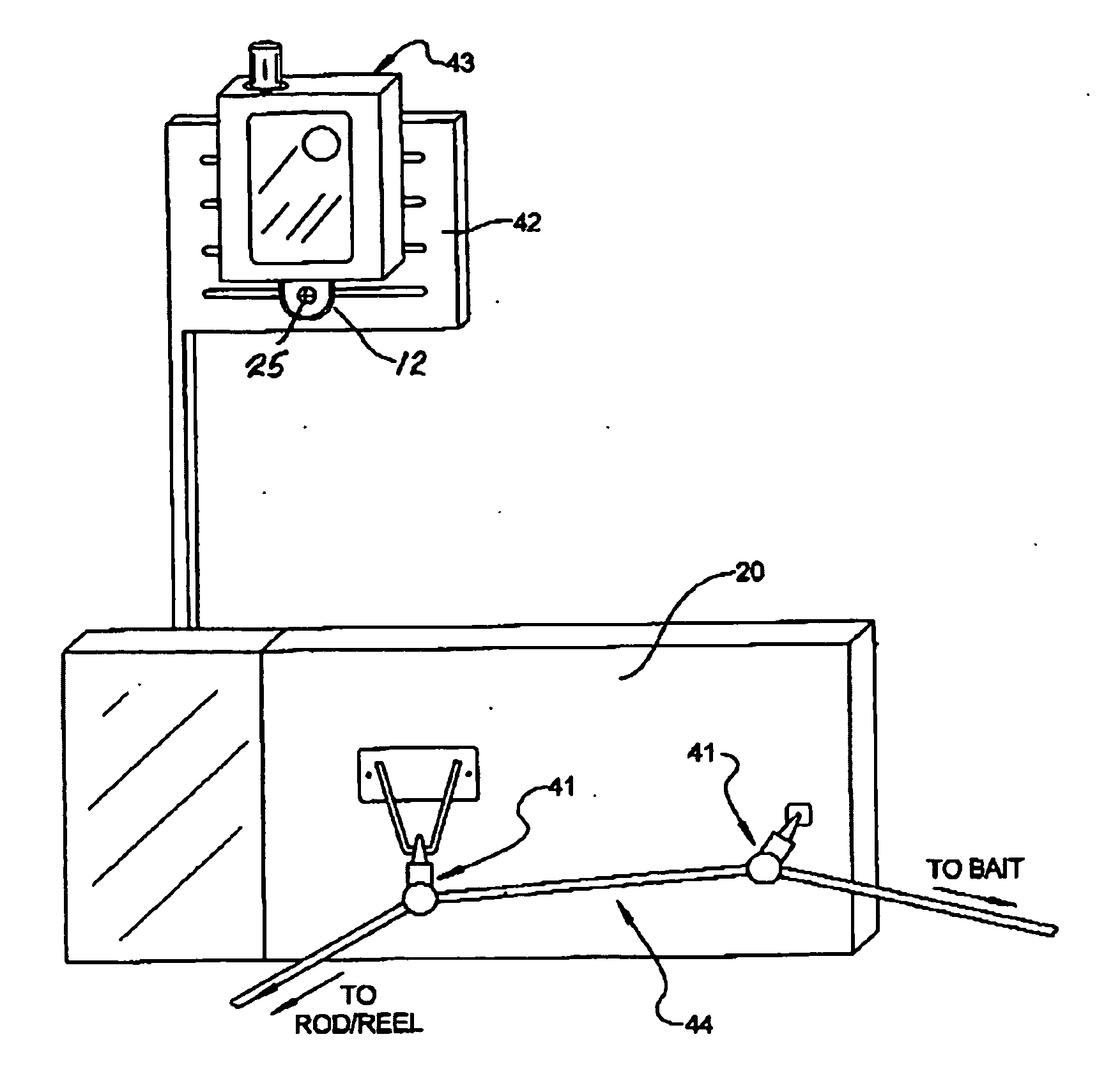
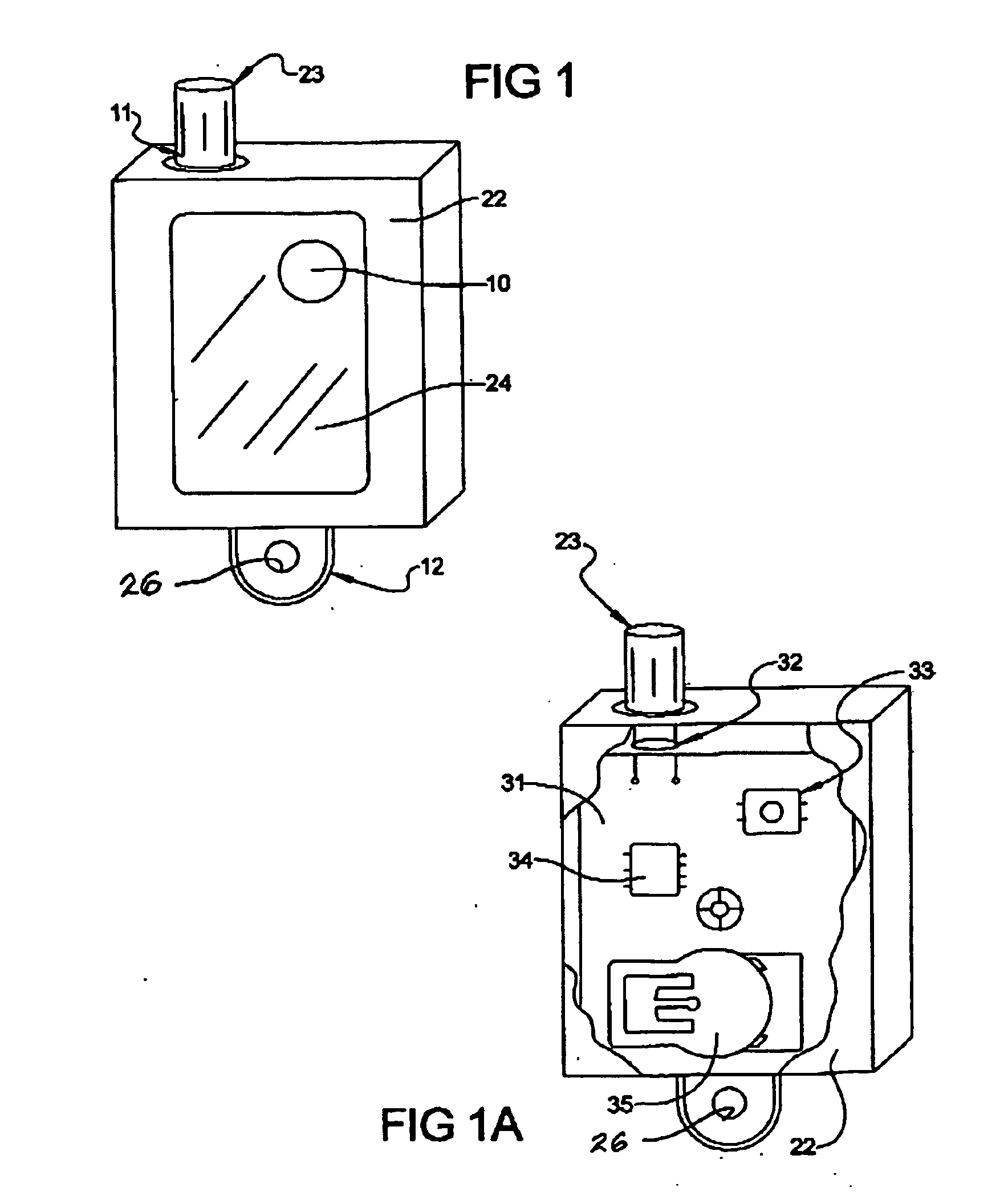
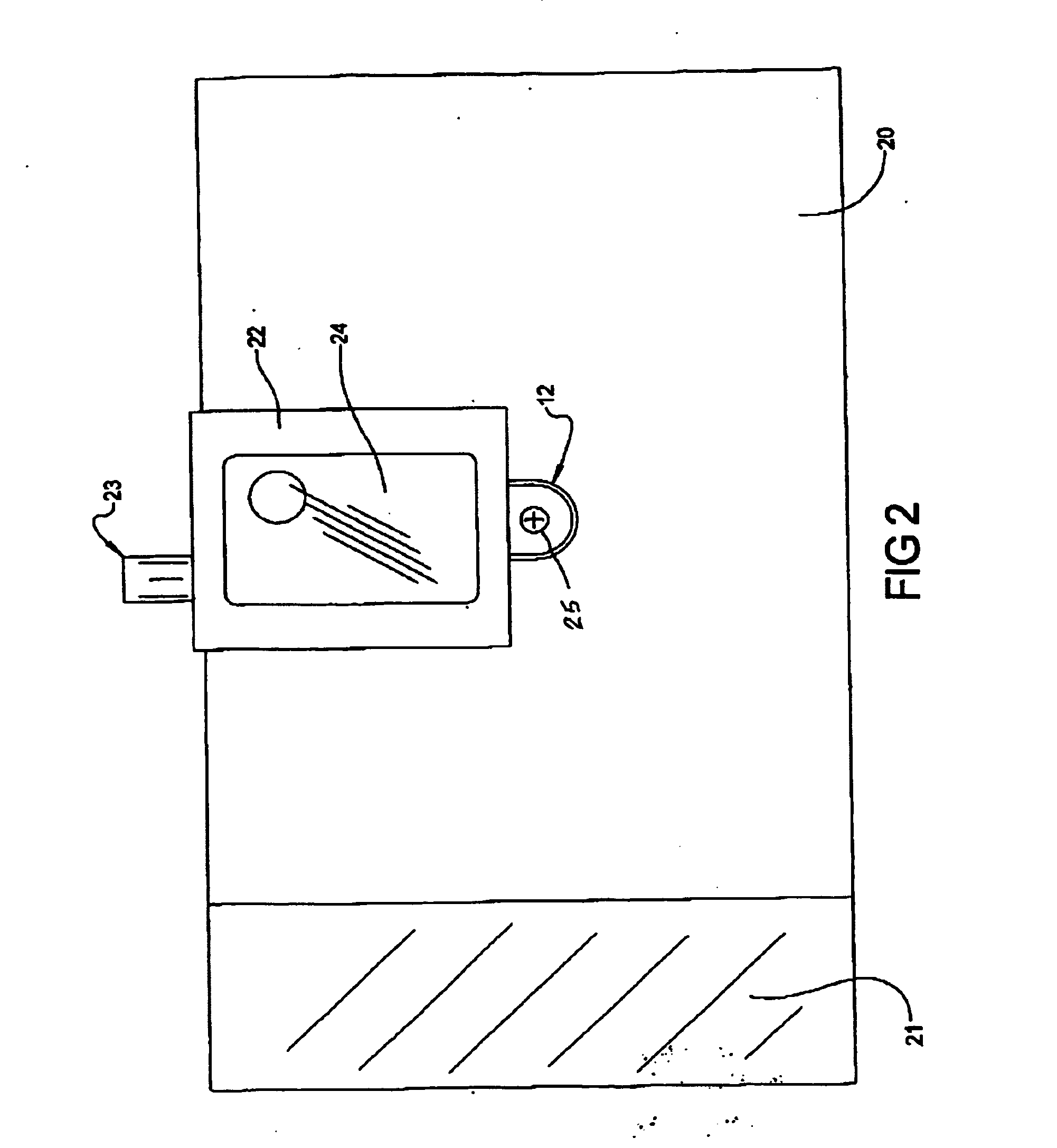
[0024] With reference to the drawings, a preferred embodiment is shown in FIG. 1. 22 is a rugged waterproof enclosure to house the electronics of the invention. 23 is a generally clear or colored lens for the light source. 11 is an o-ring for additional waterproofing of the hole in enclosure 22 to allow the lens 23 to protrude. 24 is a reflective label covering a dome switch 10 utilized for tactile feel. 12 is a flange possessing a hole that is part of the enclosure 22 for mounting to a planer board or flag of a planer board.
[0025...
PUM
 Abstract
Description
Claims
Application Information