Heavy duty tire
a tire and tire body technology, applied in the field of heavy duty tires, can solve the problems of difficult inflating the tire, and achieve the effect of increasing the usable years and preventing the bead portion from deformation
Inactive Publication Date: 2006-09-21
SUMITOMO RUBBER IND LTD
View PDF4 Cites 20 Cited by
- Summary
- Abstract
- Description
- Claims
- Application Information
AI Technical Summary
Benefits of technology
[0008] It is, therefore, a main object of the present invention to provide a heavy duty tire which can maintain a contact enou
Problems solved by technology
The deformation of the bead portion becomes large by the increase of usable years and generates a gap between the toe “c” of the bead portion and the rim with this, whe
Method used
View moreImage
Smart ImageViewing Examples

Examples
 PUM
 Abstract
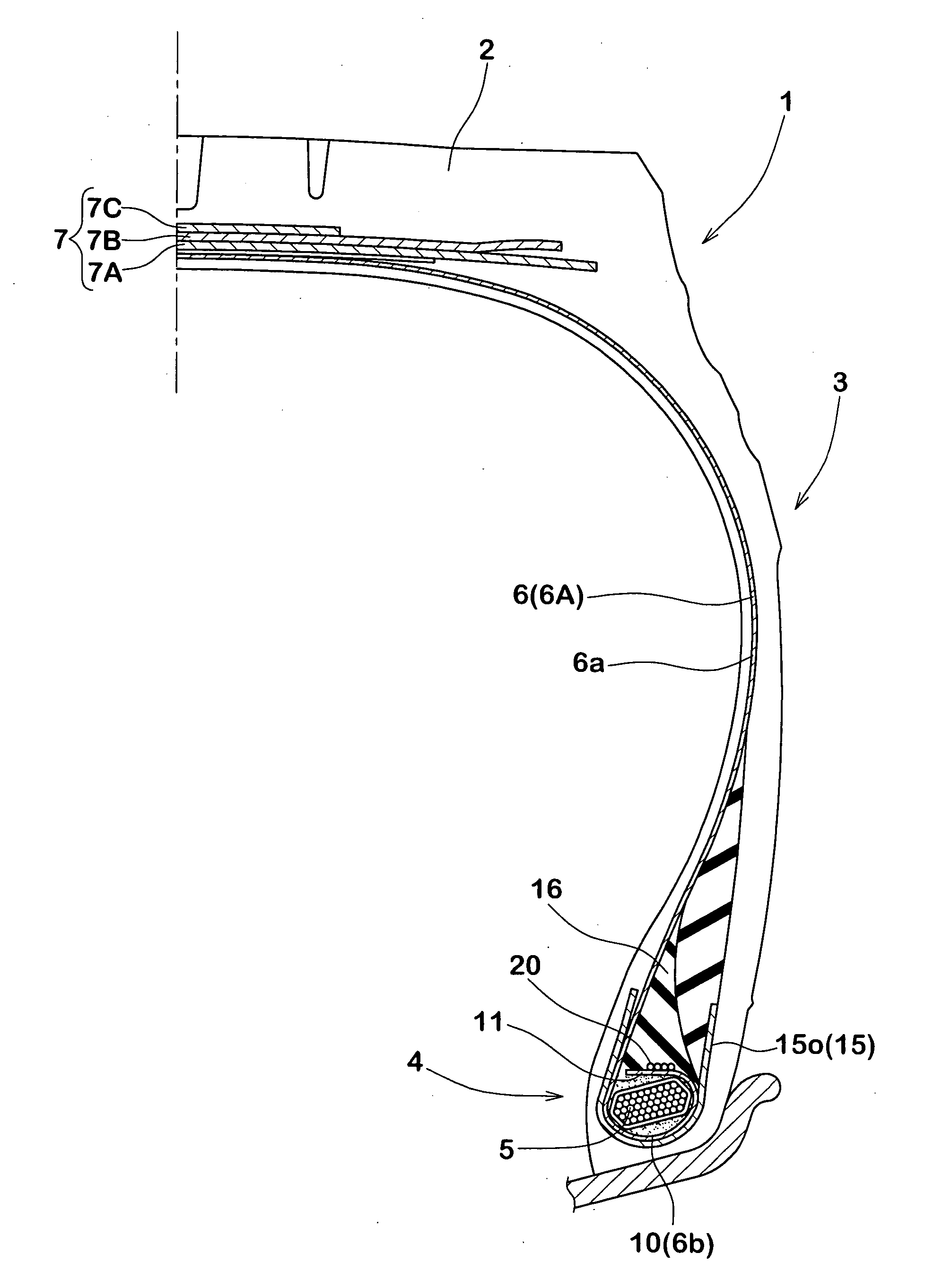
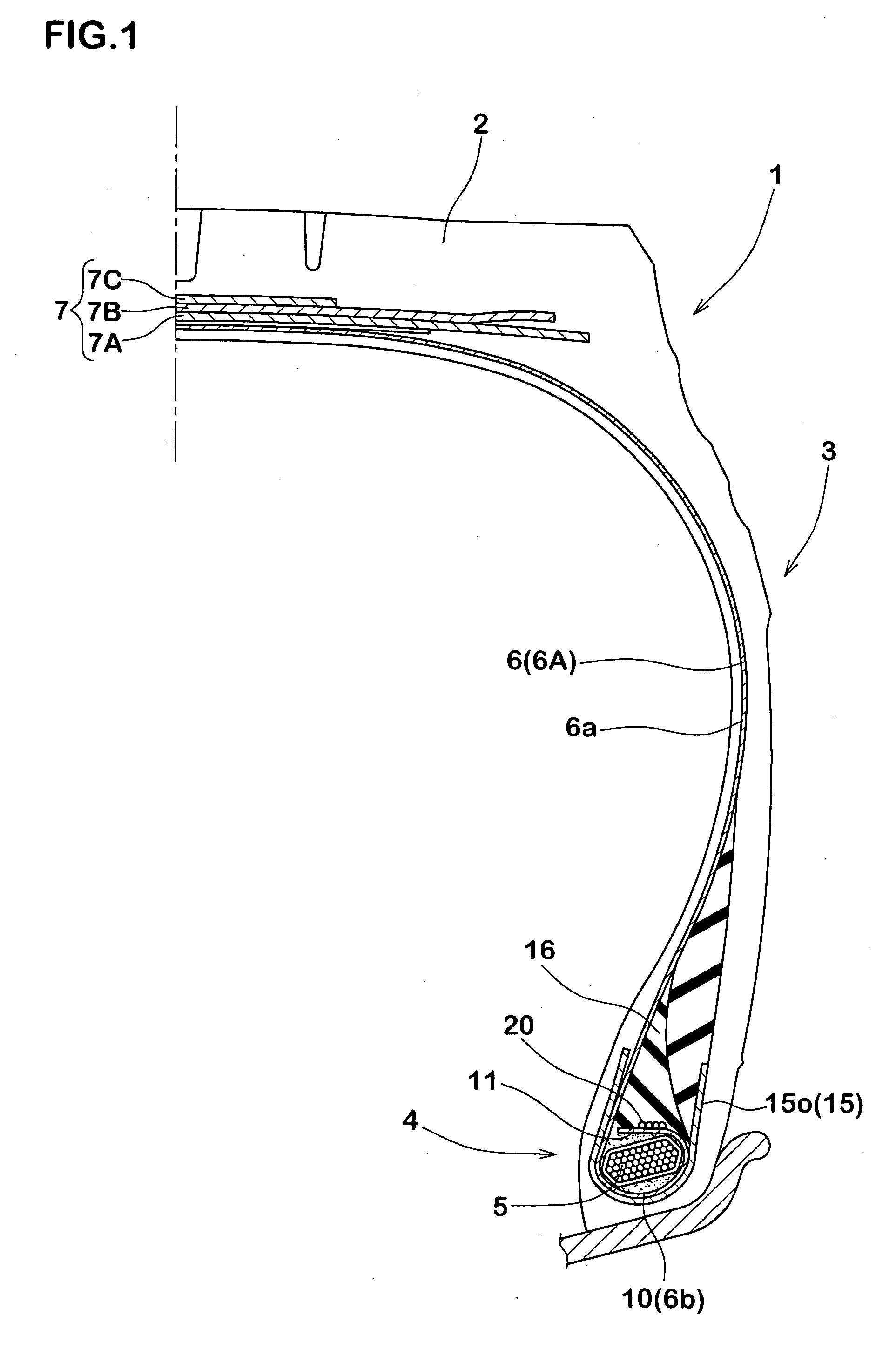
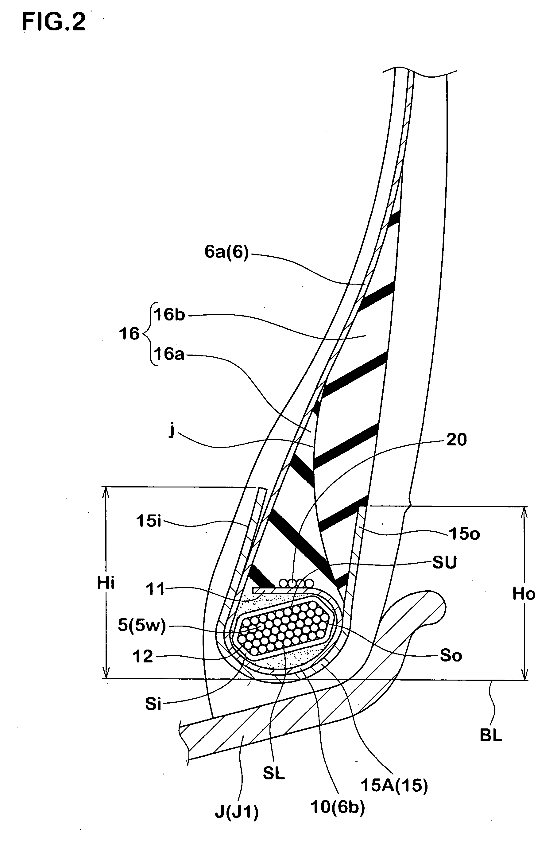
A heavy duty tire comprises a tread portion, a pair of sidewall portions, a pair of bead portions each with a bead core therein, the bead core with an aspect ratio (HC1/WC) of from 0.43 to 0.58, and a carcass comprising a carcass ply of cords extending between the bead portions and turned up around a bead core in each bead portion from the inside to outside of the tire so as to form a pair of turnup portions and a main portion therebetween, the turnup portion comprising a turnup main-part extending along an axially inner surface, a radially inner surface and an axially outer surface of the bead core smoothly, and a turnup sub-part extending from the turnup main-part toward the main portion near the radially outer surface of the bead core.
Description
BACKGROUND OF THE INVENTION [0001] 1. Field of the Invention [0002] The present invention relates to a heavy duty tire which can reduce deformation of the bead portion caused by the increase in usable years. [0003] 2. Description of the Prior Art [0004] In FIG. 11, there is shown a structure of a bead portion of a conventional heavy duty tire. The bead portion comprises a carcass ply “a” including a main portion a1 and a pair of turnup portions a2 each wound around a bead core b. [0005] In such a structure, since an outer end a2e of the turnup portion “a2” is positioned near a radially outer surface of the bead core b, a stress applied to the end a2e of the turnup portion at a time when the bead portion is deformed is small. Accordingly, it is possible to prevent some damages such as a loose from the end a2e or the like. [0006] However, in such a bead structure, a large moment M around the center b1 of the cross section of the bead core b tends to be generated by tension F of the ca...
Claims
Login to view more Application Information
Patent Timeline
 IPC IPC(8): B60C15/00
CPCB60C9/2006B60C15/0027Y10T152/10819B60C2015/044Y10T152/10846B60C15/04B60C15/0607
Inventor YOSHIKAWA, HIDEAKIMARUOKA, KIYOTO
Owner SUMITOMO RUBBER IND LTD
- R&D Engineer
- R&D Manager
- IP Professional
Why Eureka
- Industry Leading Data Capabilities
- Powerful AI technology
- Patent DNA Extraction
Try Eureka
Browse by: Latest US Patents, China's latest patents, Technical Efficacy Thesaurus, Application Domain, Technology Topic.
© 2024 PatSnap. All rights reserved.Legal|Privacy policy|Modern Slavery Act Transparency Statement|Sitemap