Pneumatic radial tire

a radial tire and pneumatic technology, applied in the direction of tire beads, heavy-duty vehicles, vehicle components, etc., can solve the problems of separation and cause separation, and achieve the effect of suppressing separation in the inner position, reducing rigidity steps, and high rubber hardness

Inactive Publication Date: 2012-12-20
TOYO TIRE & RUBBER CO LTD
View PDF10 Cites 24 Cited by
  • Summary
  • Abstract
  • Description
  • Claims
  • Application Information

AI Technical Summary

Benefits of technology

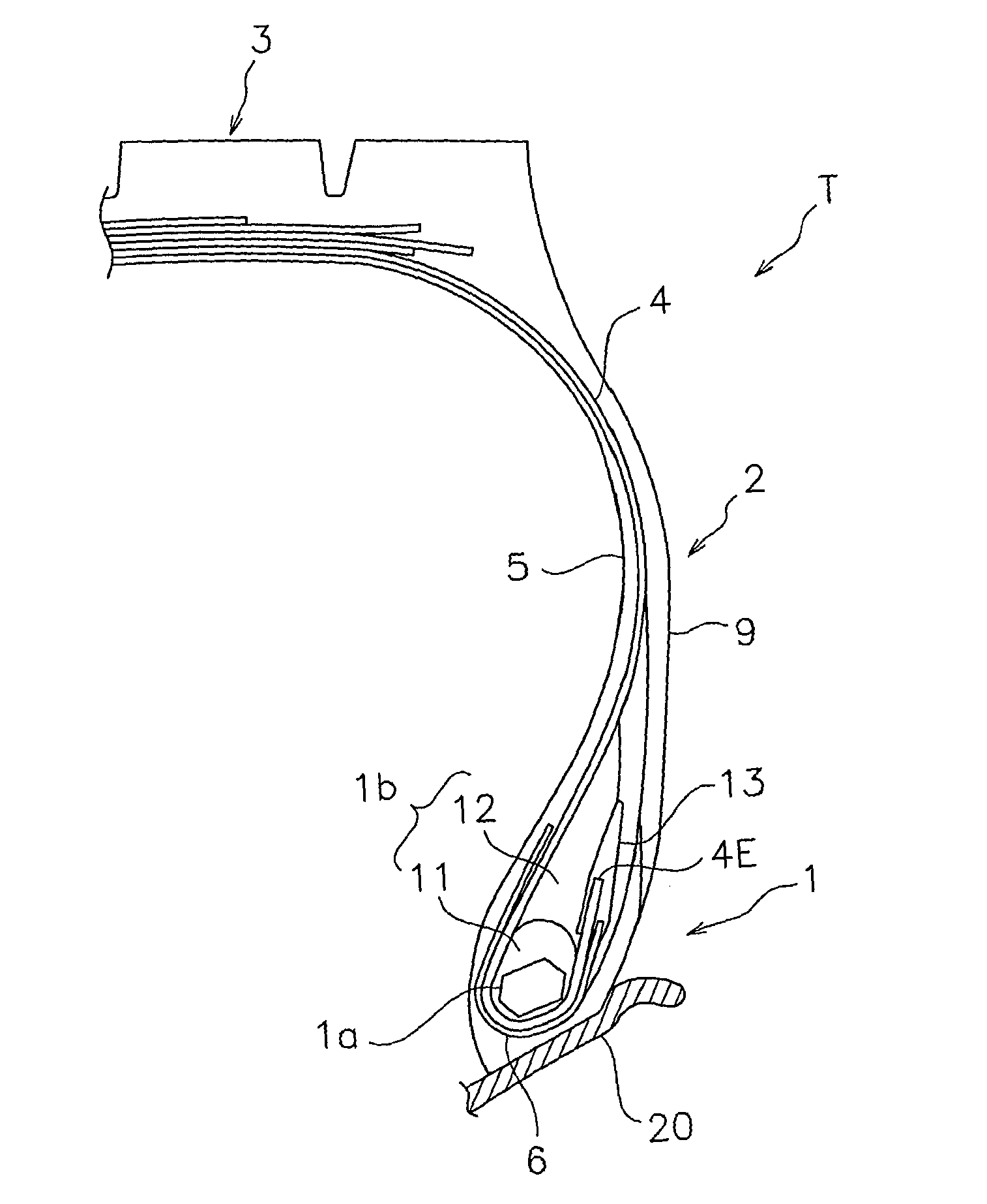
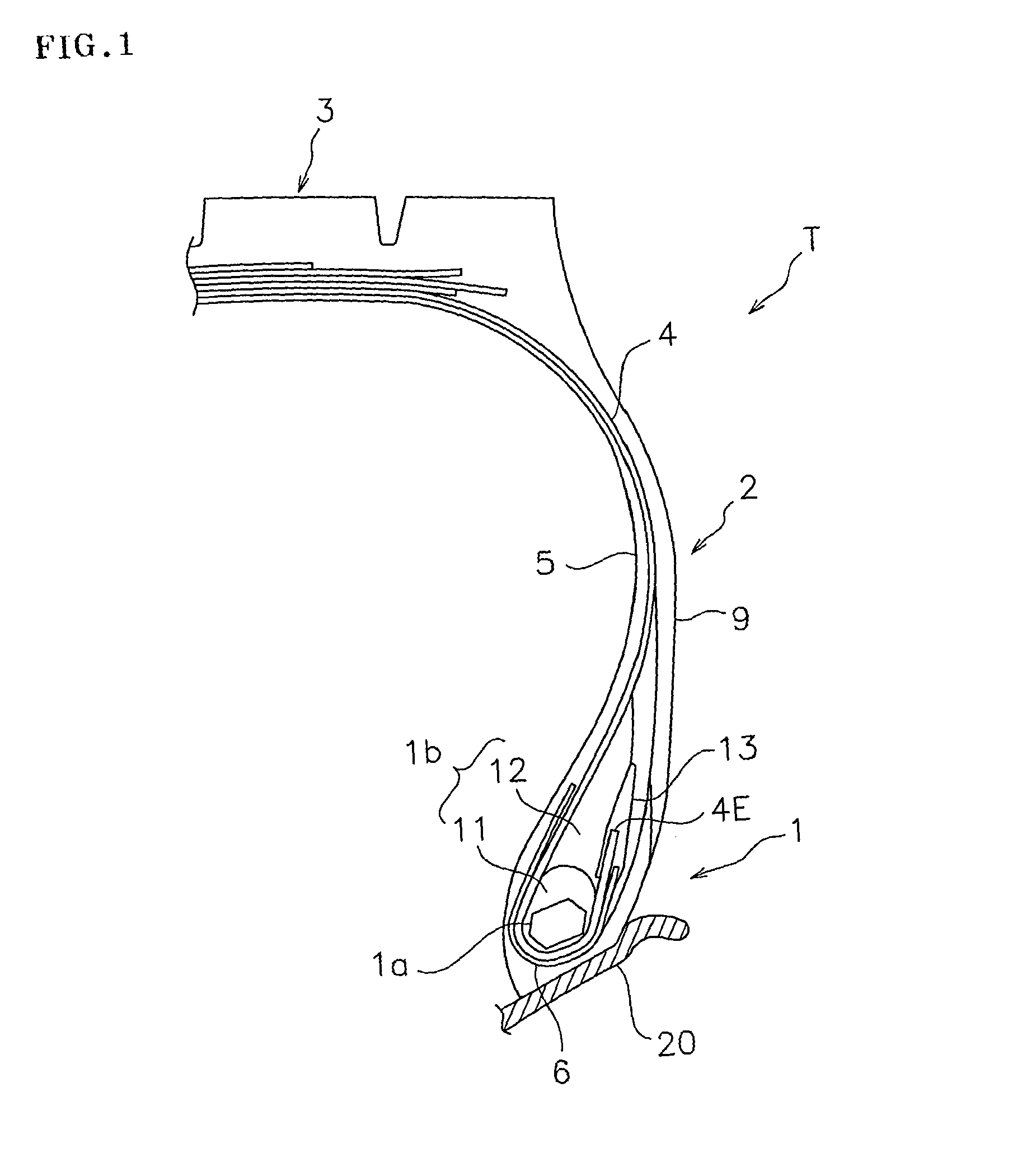
[0013]Accordingly, an object of the present invention is to provide a pneumatic radial tire which prevents separation in an inner position of a wound-up portion of a carcass ply and is excellent in a durability of a bead portion.
[0015]According to the pneumatic radial tire of the present invention, since the rubber pad having the higher rubber hardness than the upper filler extends to the inner side in the tire diametrical direction than the upper end of the lower filler while coming into contact with the inner side of the wound-up portion of the carcass ply, it is possible to reduce a rigidity step in the tire diametrical direction in the bead portion so as to suppress separation in the inner position of the wound-up portion of the carcass ply.
[0016]In the pneumatic radial tire in accordance with the present invention, it is preferable that the rubber hardness of the lower filler is between 85 and 95, the rubber hardness of the upper filler is between 56 and 66, and the rubber hardness of the rubber pad is between 68 and 78. Even in the case that the hardness difference between the lower filler and the upper filler is large as mentioned above, according to the present invention, it is possible to well reduce the rigidity step in the tire diametrical direction so as to prevent the separation in the inner position of the wound-up portion of the carcass ply, by setting the rubber pad as mentioned above. In the present invention, the rubber hardness indicates a hardness at 23° C. in accordance with a provision of JISK6253.
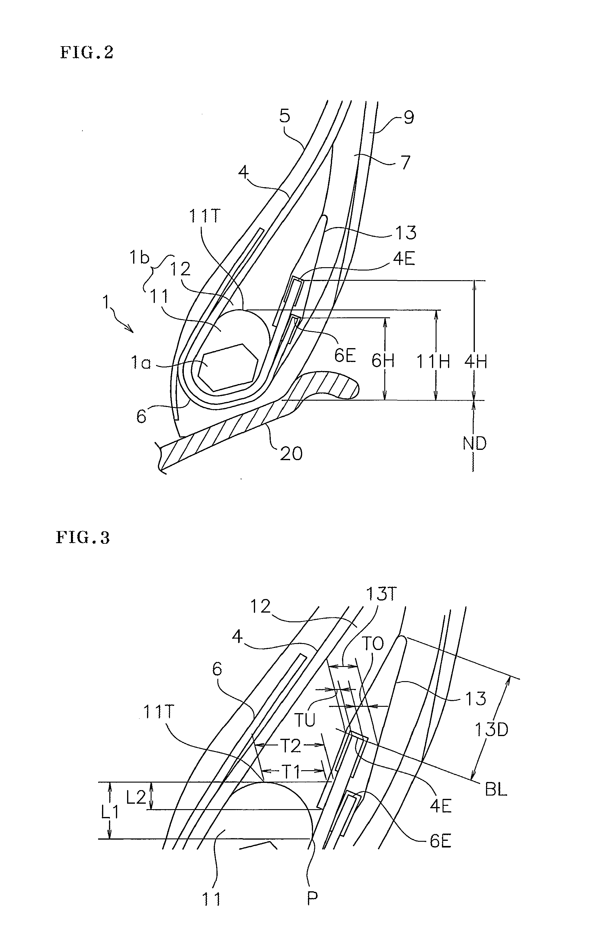
[0017]In the pneumatic radial tire in accordance with the present invention, it is preferable that based on a rim reference diameter, each of a ratio of a height of the upper end of the lower filler with respect to a wound-up height of the carcass ply, and a ratio of a wound-up height of the chafer with respect to the wound-up height of the carcass ply is between 0.5 and 0.8. Since these ratios are equal to or more than 0.5, a height of the upper end of the lower filler and the wound-up height of the chafer can be properly secured, and a generation of a trouble beginning at the wound-up end of the carcass ply can be well suppressed. Further, since these ratios are equal to or less than 0.8, it is possible to prevent the upper end of the lower filler and the wound-up end of the chafer from coming too close to the wound-up end of the carcass ply, and it is possible to suppress the reduction of the durability of the wound-up end of the carcass ply.
[0018]In the pneumatic radial tire in accordance with the present invention, it is preferable that a relationship 0.05<(T2−T1) / T2<0.5 is satisfied between a thickness T1 which is measured as a distance in a tire axial direction from the upper end of the lower filler to the rubber pad, and a thickness T2 which is measured as a distance in a tire axial direction from the upper end of the lower filler to the wound-up portion of the carcass ply. According to the structure mentioned above, it is possible to secure the thickness of the rubber pad which is arranged in the inner side of the wound-up portion of the carcass ply so as to well suppress the separation in the inner position of the wound-up portion of the carcass ply.
[0019]In the pneumatic radial tire in accordance with the present invention, it is preferable that the rubber pad comes into contact with the lower filler while increasing its thickness toward an inner side in the tire diametrical direction, in an inner side of the wound-up portion of the carcass ply. According to the structure mentioned above, it is possible to effectively suppress the separation in the inner position of the wound-up portion of the carcass ply by securing the thickness of the rubber pad while covering the inner side of the wound-up portion of the carcass ply with the rubber pad.

Problems solved by technology

Conventionally, in a pneumatic radial tire which is particularly used in a vehicle having a heavy weight, such as an industrial vehicle or a construction vehicle, there has been fear that a trouble such as separation is caused from a wound-up end of a carcass ply wound up around a bead core.
However, since a stress acting on the wound-up end is hard to be dispersed in the steel chafer in comparison with the nylon chafer, and there is fear that the separation is generated from the wound-up end, it is necessary to set the wound-up height low in the case of employing the steel chafer 36, as shown in FIG. 7.

Method used


Image

  • Pneumatic radial tire
  • Pneumatic radial tire
  • Pneumatic radial tire

Examples


example

[0048]Since a durability test of the bead portion was carried out in order to specifically show the structure and the effect of the present invention, a description will be given below. A tire used for the test had a size of 11R22.5 16PR, and was installed to a rim having a size of 7.5×22.5.

[0049]In the durability test, the tire was dismounted after traveling at 200,000 km under a condition of an internal pressure of 800 kPa and a load of 29.4 kN, and a coverage (an area rate of the rubber coating the ply cord) in the inner side of the wound-up portion of the carcass ply was measured. An evaluation was carried out by an index number at the time of setting a result of a comparative example to 100, the larger the numerical value is, the greater the coverage is, which indicates that the generation and the progress of the separation are suppressed.

[0050]As shown in FIG. 5, a comparative example was set to one having the same structure as an example 1 except the structure in which the ru...


PUM

PropertyMeasurementUnit
angleaaaaaaaaaa
angleaaaaaaaaaa
thicknessaaaaaaaaaa

Abstract

A pneumatic radial tire has a rubber filler includes a lower filler and an upper filler. The lower filler surrounds a bead core and has a round cross sectional shape. The upper filler has a lower rubber hardness than the lower filler. A chafer is wound up around the bead core outside of a carcass ply and includes a metal cord. A wound-up end of the carcass ply is arranged radially outside of an upper end of the lower filler and a wound-up end of the chafer. A rubber pad has a higher rubber hardness than the upper filler and sandwiches the wound-up end of the carcass ply. The rubber pad extends to radially inside of the upper end of the lower filler and contacts with an inside of a wound-up portion of the carcass ply.

Description

BACKGROUND OF THE INVENTION[0001]1. Field of the Invention[0002]The present invention relates to a pneumatic radial tire which is characterized by a structure of a bead portion and has a high durability. The present invention is particularly useful for a pneumatic radial tire for a heavy load.[0003]2. Description of the Related Art[0004]Conventionally, in a pneumatic radial tire which is particularly used in a vehicle having a heavy weight, such as an industrial vehicle or a construction vehicle, there has been fear that a trouble such as separation is caused from a wound-up end of a carcass ply wound up around a bead core. Accordingly, it is generally carried out to intend an improvement of a durability of the bead portion by arranging a reinforcing layer called a chafer along the carcass ply. Patent Document 1 and 2 disclose such a chafer.[0005]Further, in Patent Document 3 by the applicant of the present application, in order to suppress a shear strain of the wound-up end of the ...

Claims


Application Information

Patent Timeline
Patent Type & Authority Applications(United States)
IPC IPC(8): B60C15/06
CPCB60C15/0635B60C15/0607B60C2015/0621B60C2015/0625Y10T152/10846B60C15/06Y10T152/10837Y10T152/10828B60C15/0009B60C2200/06
Inventor NISHIO, TAIICHI
Owner TOYO TIRE & RUBBER CO LTD
Why Eureka
Try Eureka