Collapsible expansion cone

a cone and expansion cone technology, applied in the field of oil and gas exploration, can solve the problems of increased drilling rig time, increased cost, and required equipment changes,

Inactive Publication Date: 2006-09-21
WATSON BROCK WAYNE +1
View PDF99 Cites 25 Cited by
  • Summary
  • Abstract
  • Description
  • Claims
  • Application Information

AI Technical Summary

Problems solved by technology

Such a large borehole diameter involves increased costs due to heavy casing handling equipment, large drill bits and increased volumes of drilling fluid and drill cuttings.
Moreover, increased drilling rig time is involved due to required cement pumping, cement hardening, required equipment changes due to large variations in hole diameters drilled in the course of the well, and the large volume of cuttings drilled and removed.

Method used


Image

  • Collapsible expansion cone
  • Collapsible expansion cone
  • Collapsible expansion cone

Examples


Embodiment Construction

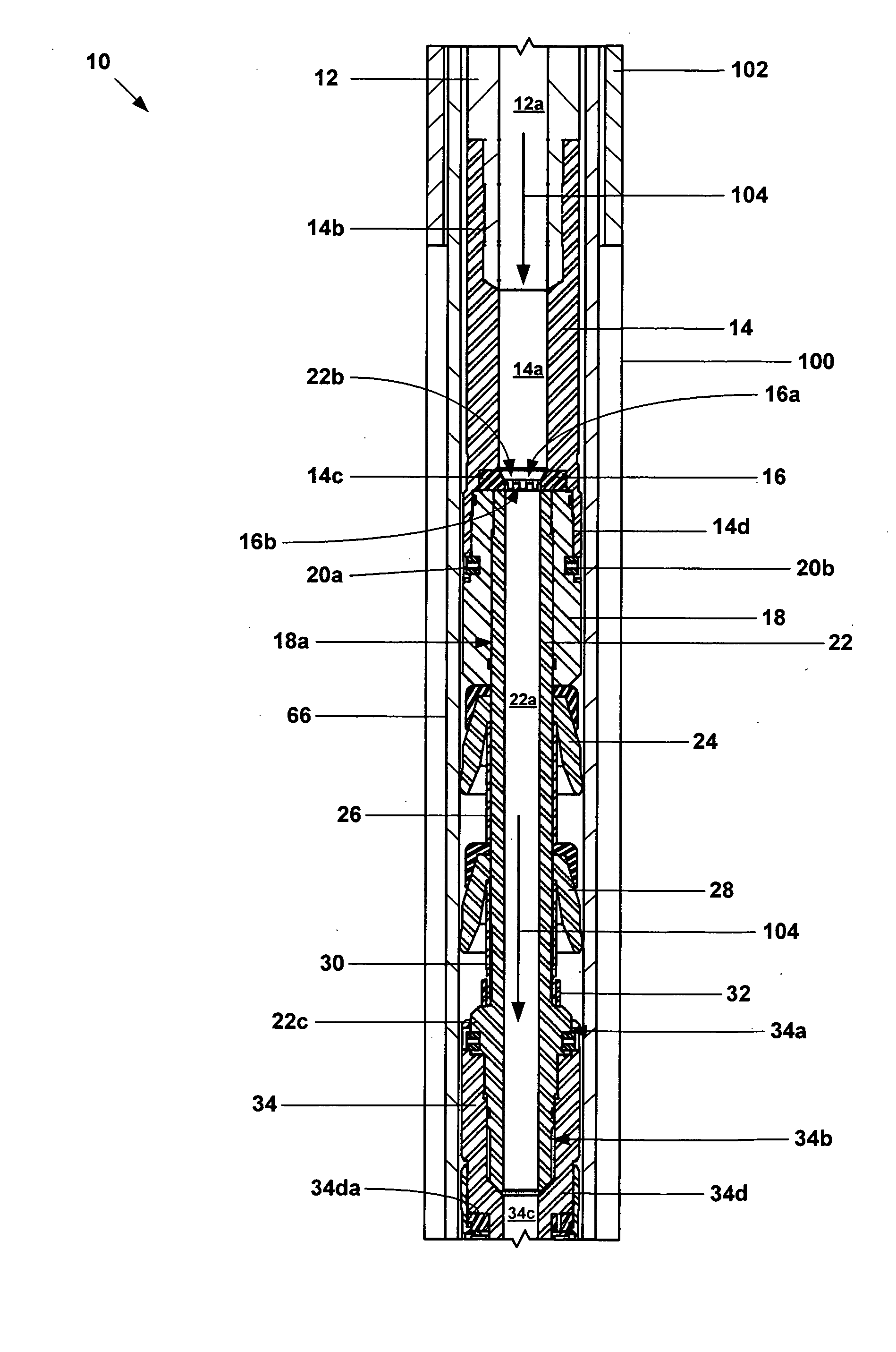
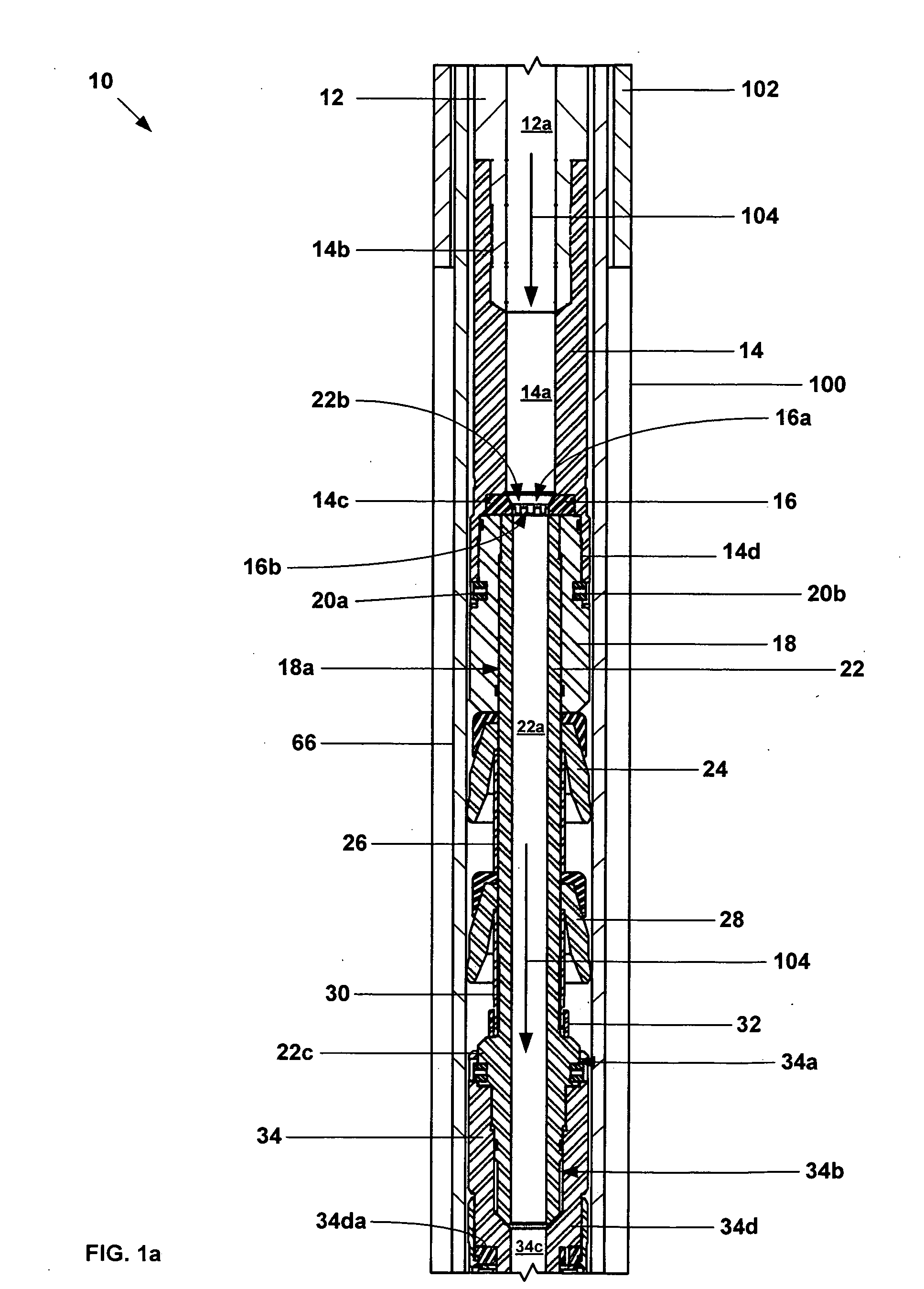
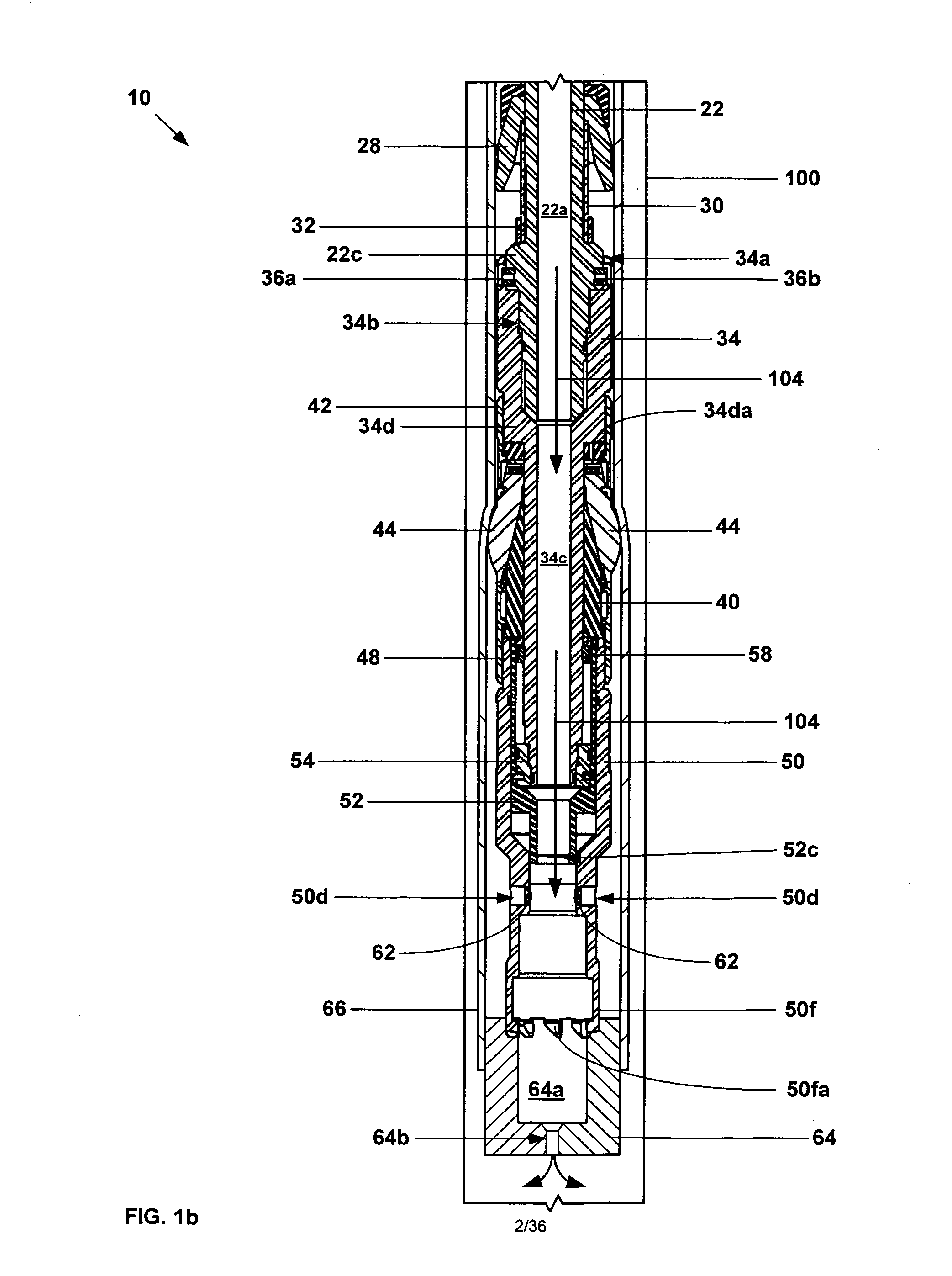
[0046] Referring to FIGS. 1a, 1b, 2a, 2b, 3, 3a, 4, 4a, 5, 6, 7a, 7b, 7c, 7d, 7e, 7f, 8a, 8b, 8c, 8d, 8e, and 9, an exemplary embodiment of an apparatus 10 for radially expanding and plastically deforming a tubular member includes a tubular support member 12 that defines a passage 12a. An end of the tubular support member 12 is coupled to an end of a safety collar 14 that defines a passage 14a, a recess 14b at one end for receiving the end of the tubular support member, and recesses 14c and 14d at another end.

[0047] A torque plate 16 is received within and is coupled to the recess 14c of the safety collar 14 that defines a passage 16a and a plurality of meshing teeth 16b at one end. An end of an upper mandrel collar 18 is received with and is coupled to the recess 14d of the safety collar 14 proximate and end of the torque plate 16 that defines a passage 18a. Torque pins 20a and 20b further couple the end of the upper mandrel collar 18 to the end of the safety collar 14.

[0048] An ...


PUM

PropertyMeasurementUnit
pressureaaaaaaaaaa
operating pressureaaaaaaaaaa
diameteraaaaaaaaaa

Abstract

An apparatus for radially expanding and plastically deforming an expandable tubular member includes a collapsible expansion cone.

Description

CROSS REFERENCE TO RELATED APPLICATIONS [0001] The present application is the National Stage for PCT patent application serial no. PCT / US2003 / 018530, attorney docket no. 25791.108.02, filed on 12 Jun. 2003, which claimed the benefit of the filing date of U.S. provisional patent application Ser. No. 60 / 387,961, attorney docket no 25791.108, filed on Jun. 12, 2002, the disclosures of which are incorporated herein by reference. [0002] The present application is a continuation-in-part of U.S. utility patent application Ser. No. 10 / 507,567, attorney docket no. 25791.95.03, filed on , Feb. 19, 2003 which claimed the benefit of the filing date of U.S. provisional patent application serial no. 60 / 363,829, attorney docket no. 25791.95, filed on Mar. 13, 2002, which was a continuation-in-part of each of the following: U.S. utility patent application Ser. No. 10 / 495,347, attorney docket no. 25791.87.05, filed on Nov. 12, 2002, which claimed the benefit of the filing date of U.S. provisional pa...

Claims


Application Information

Patent Timeline
Patent Type & Authority Applications(United States)
IPC IPC(8): E21B43/10B29CE21BE21B7/20E21B29/00E21B33/126
CPCE21B33/126E21B43/105
Inventor WATSON, BROCK WAYNEBRISCO, DAVID PAUL
Owner WATSON BROCK WAYNE
Why Eureka
Try Eureka