Active venting apparatus and method for airbag systems

a technology of active venting and airbag system, which is applied in the direction of pedestrian/occupant safety arrangement, vehicular safety arrangement, transportation and packaging, etc., can solve the problems of comparatively less venting, limited reliability, and limited use of known variable venting system, so as to quickly adapt the stiffness of the cushion

Inactive Publication Date: 2006-09-21
AUTOLIV ASP INC
View PDF23 Cites 13 Cited by
  • Summary
  • Abstract
  • Description
  • Claims
  • Application Information

AI Technical Summary

Benefits of technology

[0014] The apparatus and method of the present invention have been developed in response to the present state of the art, and in particular, in response to the problems and needs in the art that have not yet been fully solved by currently available airbag modules. Thus, it is an overall purpose of the present invention to provide an airbag module that remedies the shortcomings of the prior art. Such an airbag module may rapidly adapt the stiffness of the cushion according to one or more factors such as impact velocity, occupant weight, and occupant position.
[0018] The bolt has a bore with an initiator portion that captures an initiator; the initiator ignites in response to receipt of an activation signal. The bolt is designed in such a way that the head detaches from the shank when the initiator ignites. The bore also has a retaining portion through which the initiator cannot pass; the retaining portion receives an ignition plug that conveys the activation signal to the initiator. The bolt is constructed of a moldable material such as plastic. The bolt may be formed by molding the plastic around the initiator so that the initiator need not be inserted into the bore of the bolt in a separate process.
[0020] For example, if the impact occurs at high velocity or the vehicle occupant is comparatively heavy, a stiffer cushion may provide the best protection, and the closure mechanism may not be actuated. However, if the impact is a low velocity collision and / or the occupant is lighter, the closure mechanism is actuated to permit venting through the flexible venting tube, thereby reducing the stiffness of the inflatable protection zone.
[0027] Through the use of the airbag modules and associated methods of the present invention, the stiffness of airbag cushions may be rapidly adapted to suit the circumstances of the collision. Hence, vehicle occupants can receive optimal protection under a wide variety of conditions. Such benefits are obtained with a comparatively small increase in the cost and complexity of the airbag module.

Problems solved by technology

However, for high speed collisions, a stiffer cushion is needed to more rapidly absorb the occupant's velocity; hence, comparatively less venting is desirable.
Unfortunately, known variable venting systems are limited in many respects.
For example, many such systems utilize an actuation mechanism that is too slow to reliably permit the desired degree of venting to occur prior to impact of the occupant against the cushion.
Some variable venting systems are simply too slow to vary the cushion stiffness based upon the impact velocity, and are thus unable to adapt the stiffness of the cushion to suit the severity of the collision.
Additionally, placement of vents on the rigid module housing imposes limitations on the size, shape, and location of the vents.
Thus, the optimal degree of venting may be unobtainable.
More precisely, the vents may not be large enough to release enough gas to soften the cushion as much as may be desirable.
The vents may also be obstructed by internal components of the vehicle, thereby further reducing the degree of cushion adaptation that can be achieved.
Furthermore, many known variable venting systems are somewhat complex and expensive to produce.
The design of the airbag module may be unduly hindered by placement of the vents on the rigid module housing; such placement may interfere with the positioning of other module components such as the inflator, mounting hardware, and the like.

Method used


Image

  • Active venting apparatus and method for airbag systems
  • Active venting apparatus and method for airbag systems
  • Active venting apparatus and method for airbag systems

Examples


Embodiment Construction

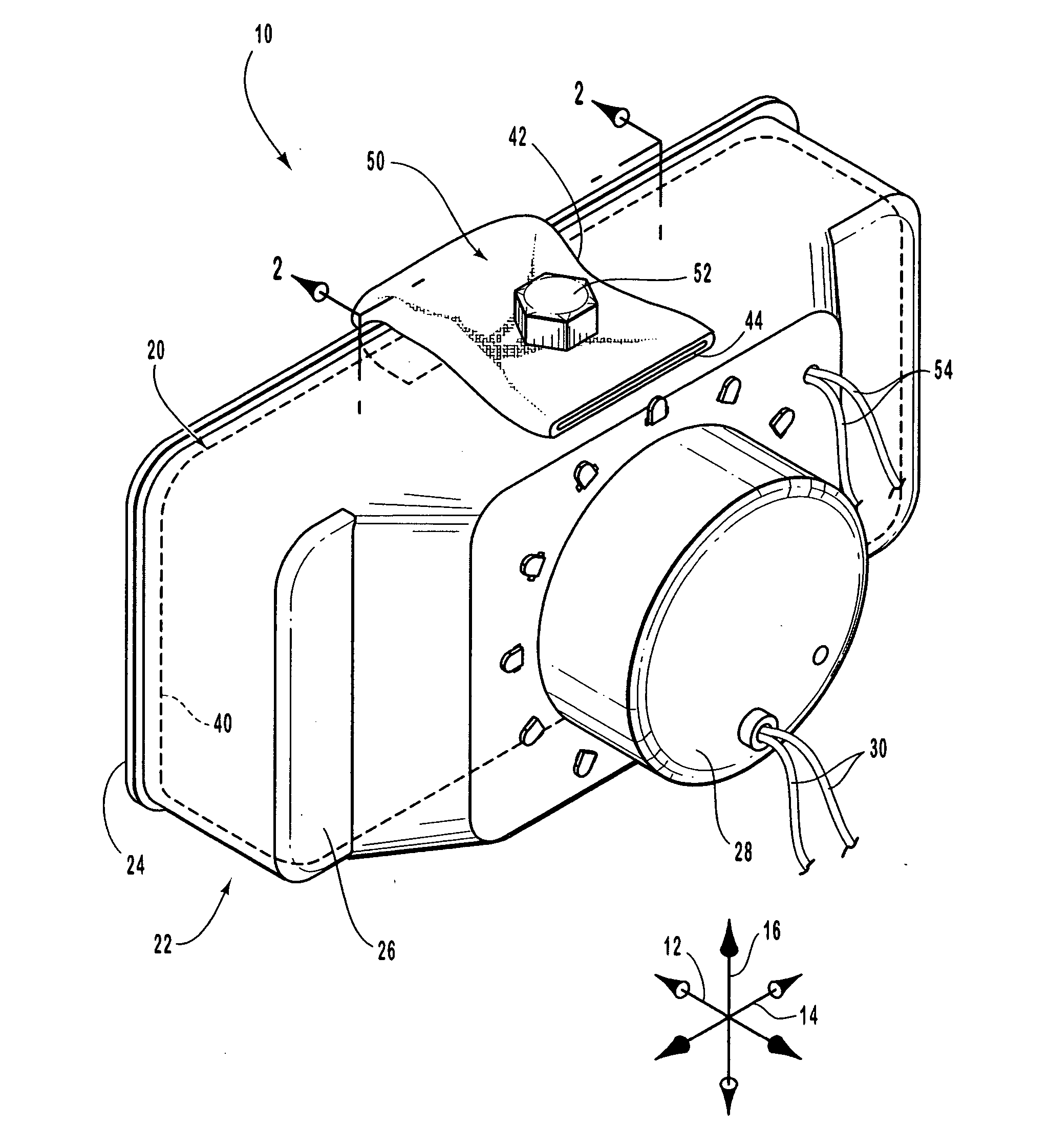
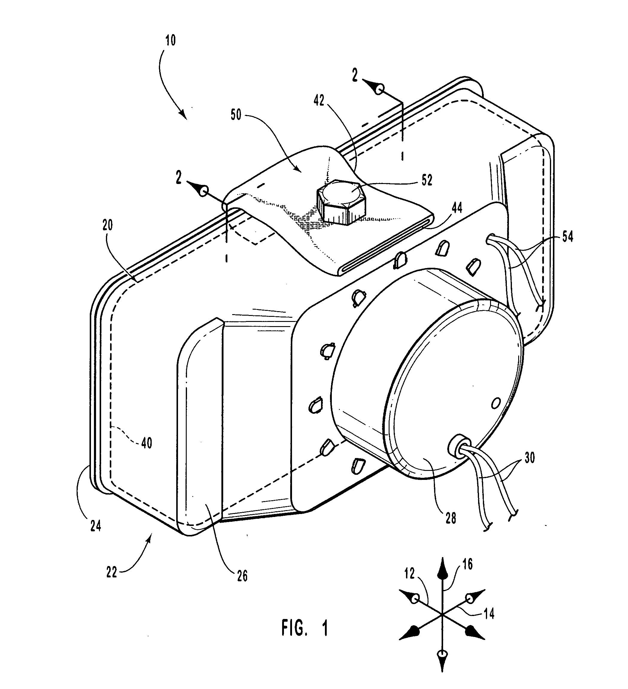
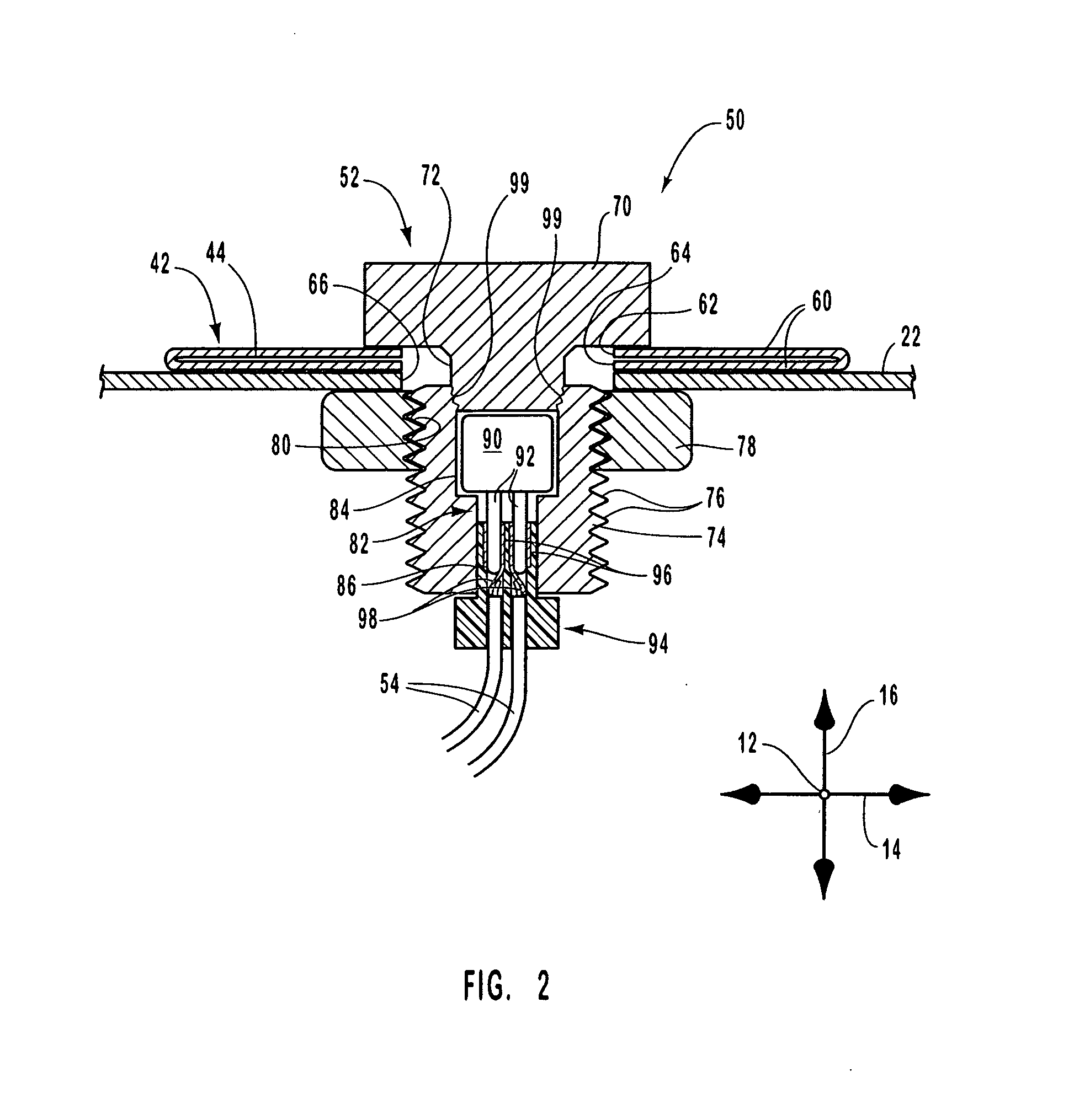
[0037] The presently preferred embodiments of the present invention will be best understood by reference to the drawings, wherein like parts are designated by like numerals throughout. It will be readily understood that the components of the present invention, as generally described and illustrated in the figures herein, could be arranged and designed in a wide variety of different configurations. Thus, the following more detailed description of the embodiments of the apparatus, system, and method of the present invention, as represented in FIGS. 1 through 7, is not intended to limit the scope of the invention, as claimed, but is merely representative of presently preferred embodiments of the invention.

[0038] The present invention utilizes a number of physical principles to enhance the cost-effectiveness and operation of airbag modules. For example, principles of momentum and acceleration are used to determine the stiffness of the cushion required to protect a vehicle occupant in a...


PUM


Abstract

Enhanced airbag modules and associated methods are provided. An airbag module according to the invention may have a cushion with an inflatable protection zone and a flexible venting tube coupled to the inflatable protection zone. A closure mechanism may be used to compress the flexible venting tube against an anchoring member, such as a housing of the airbag module or a vehicle feature, until venting through the flexible venting tube is needed. The closure mechanism may then be actuated, for example, by igniting a pyrotechnic within a specially designed bolt of the closure mechanism. The bolt may, for example, have a bore with a pyrotechnic initiator molded-in-place within the bore. The bolt may fracture to open the closure mechanism, thereby permitting inflation gas to flow out of the inflatable protection zone via the flexible venting tube.

Description

CROSS-REFERENCE TO RELATED APPLICATIONS [0001] This application is a continuation of U.S. patent application Ser. No. 10 / 150,873 filed May 17, 2002, and now issued as U.S. Pat. No. X,XXX,XXX.BACKGROUND OF THE INVENTION [0002] 1. Field of the Invention [0003] The present invention relates to systems and methods for protecting vehicle occupants from injury. More specifically, the present invention relates to devices that intelligently control gas venting from an inflatable cushion to enhance the protection provided by the cushion. [0004] 2. Description of Related Art [0005] The inclusion of inflatable safety restraint devices, or airbags, is now a legal requirement for many new vehicles. Airbags are typically installed in the steering wheel and in the dashboard on the passenger side of a car. Additionally, airbags may be installed to inflate beside the passenger to provide side impact protection, in front of the knees to protect the knees from impact, over a passenger's head, or at ot...

Claims


Application Information

Patent Timeline
Patent Type & Authority Applications(United States)
IPC IPC(8): B60R21/26B60R21/16B60R21/217B60R21/276B60R21/239F42B39/20
CPCB60R21/2171B60R21/276B60R2021/26029F42B39/20B60R21/20B60R21/205B60R21/16
Inventor DEPOTTEY, TIMOTHY A.ZIOLO, MELISSASCHNEIDER, DAVID W.SHERWIN, CHARLESGREEN, DAVID J.
Owner AUTOLIV ASP INC
Why Eureka
Try Eureka