
Image forming apparatus and a storage controlling method for information on an improper detachment of a developer cartridge to be written in a cartridge storage means

a technology of image forming apparatus and storage control, which is applied in the direction of electrographic process apparatus, instruments, optics, etc., can solve the problems of inability to precisely administer the life of the developer cartridge, and the information on the life saved in the cartridge memory of the mounted developer cartridge does not always agree with the latest data

Inactive Publication Date: 2006-09-21
SEIKO EPSON CORP
View PDF7 Cites 44 Cited by
  • Summary
  • Abstract
  • Description
  • Claims
  • Application Information

AI Technical Summary

Benefits of technology

The present invention relates to an image forming apparatus with a detachable developer cartridge. The invention aims to prevent improper detachment of the developer cartridge from the apparatus main body and ensure that an exchange of the developer cartridge has been properly completed without improper detachment. The invention also aims to prevent improper detachment when the power source is shut off unexpectedly. The technical effects of the invention include improved reliability and stability of the image forming apparatus and improved user experience.

Problems solved by technology

Accordingly, information on the life saved in the cartridge memory does not always agree with the latest data.
For example, if the reading and writing from and in the cartridge memory are performed only when the developer cartridge is detached, the information on the life saved in the cartridge memory of the mounted developer cartridge does not agree with the latest data until the developer cartridge is detached from the apparatus main body.
Therefore, the life of the developer cartridge cannot be precisely administered.
However, depending on the construction of the image forming apparatus, the developer cartridge can be improperly detached by a user before the information in the cartridge memory is updated.
Further, if the developer cartridge accidentally stops at the detachment position when power supply is inadvertently shut off during the operation, for example, due to a power failure or the maloperation of a power switch by the user, the developer cartridge may be detached by the user.
Thus, the life cannot be precisely administered even if the saved content of the cartridge memory is read when the detached developer cartridge is used again later.

Method used


Image

  • Image forming apparatus and a storage controlling method for information on an improper detachment of a developer cartridge to be written in a cartridge storage means
  • Image forming apparatus and a storage controlling method for information on an improper detachment of a developer cartridge to be written in a cartridge storage means
  • Image forming apparatus and a storage controlling method for information on an improper detachment of a developer cartridge to be written in a cartridge storage means

Examples


first preferred embodiment

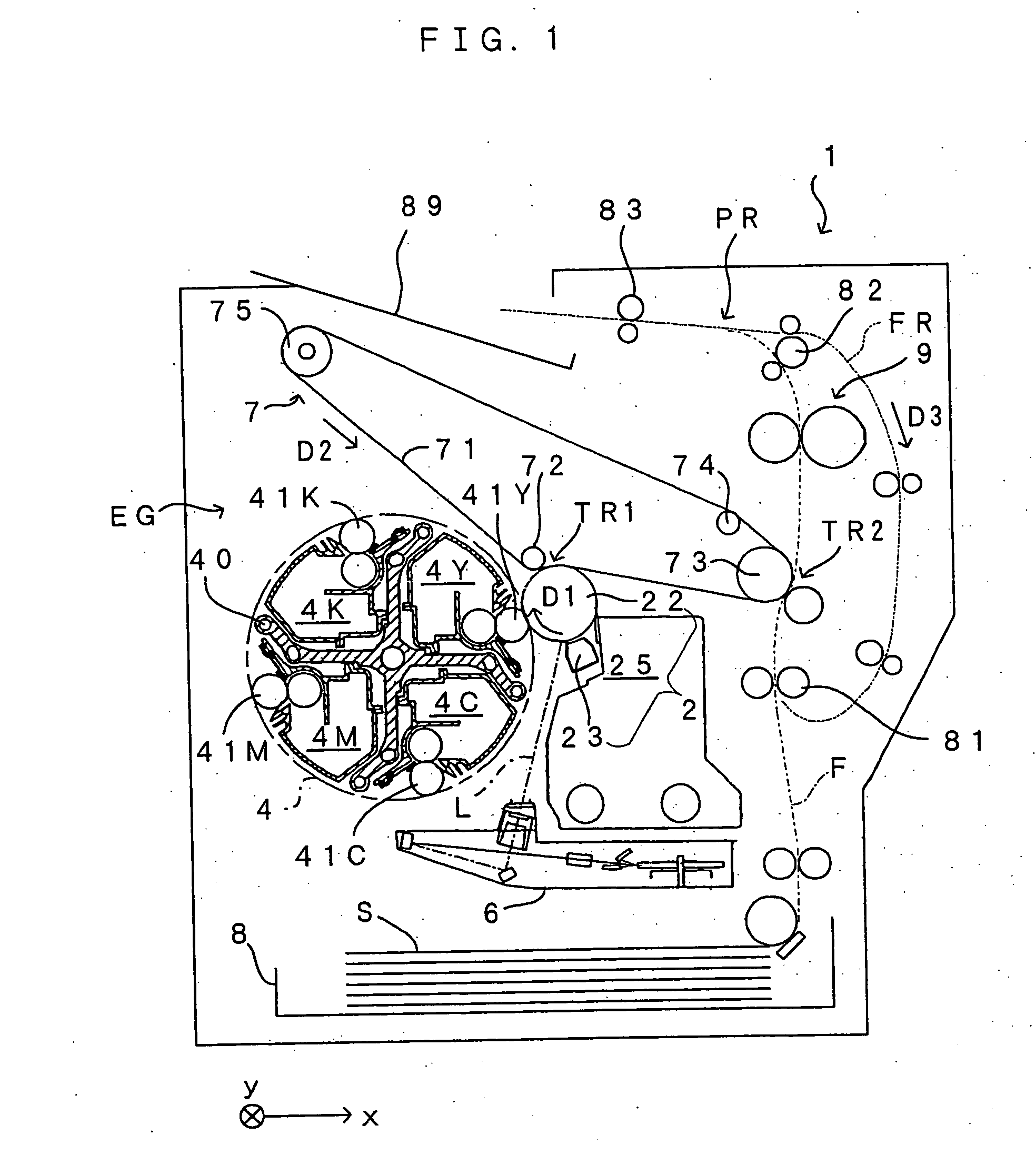
[0038]FIG. 1 is a diagram showing a first preferred embodiment of an image forming apparatus according to the invention. This apparatus is an image forming apparatus for forming a full color image by superimposing images of toners of four colors: yellow (Y), cyan (C), magenta (M) and black (K) and forming a monochromatic image only using the black (K) toner. In this image forming apparatus, when a print command signal including an image signal is given from an external apparatus such as a host computer to a controller (CPU) 160 (see FIG. 5), an engine section EG provided in an apparatus main body 1 executes a specified image forming operation in accordance with a command from the CPU 160, whereby an image corresponding to the image signal is formed on a sheet S.

[0039] In this engine section EG, a photosensitive member 22 is rotatably provided in a direction of arrow D1 of FIG. 1. Further, a charger unit 23, a rotary developing unit 4 and a cleaning section 25 are arranged around th...

second preferred embodiment

[0100] Next, a second preferred embodiment of the image forming apparatus according to the invention is described. The construction of the image forming apparatus of the second preferred embodiment is substantially the same as that of the first preferred embodiment described with reference to FIGS. 1 to 5. The second preferred embodiment partly differs from the first preferred embodiment in its construction and operation, and the following description is centered on different points.

[0101] In this second preferred embodiment, the CPU 160 reads and writes information from and in the cartridge memories 43Y, 43C, 43M, 43K only during the cartridge exchange mode in view of how often rewriting can be made to the cartridge memories 43Y, 43C, 43M, 43K until the lives of the cartridge memories 43Y, 43C, 43M, 43K end, how often the main-body side connector 421 and the developer side connectors 42Y, 42C, 42M, 42K can be connected until the lives of these connectors end, and how often the dra...

third preferred embodiment

[0124] A third preferred embodiment of the image forming apparatus according to the invention is described. The construction of the image forming apparatus of the third preferred embodiment is substantially the same as that of the first preferred embodiment described with reference to FIGS. 1 to 5. A procedure of entering the cartridge exchange mode and a procedure of the cartridge exchange mode in the third preferred embodiment are the same as those of the second preferred embodiment described with reference to FIGS. 10 to 14. The third preferred embodiment partly differs from the first and second preferred embodiments in its construction and operation, and the following description is centered on different points.

[0125] In this third preferred embodiment, a nonvolatile memory as described in the first preferred embodiment is used as the main-body memory 161 (see FIG. 5).

[0126] In this third preferred embodiment, the CPU 160 reads and writes information from and in the cartridge ...


PUM


Abstract

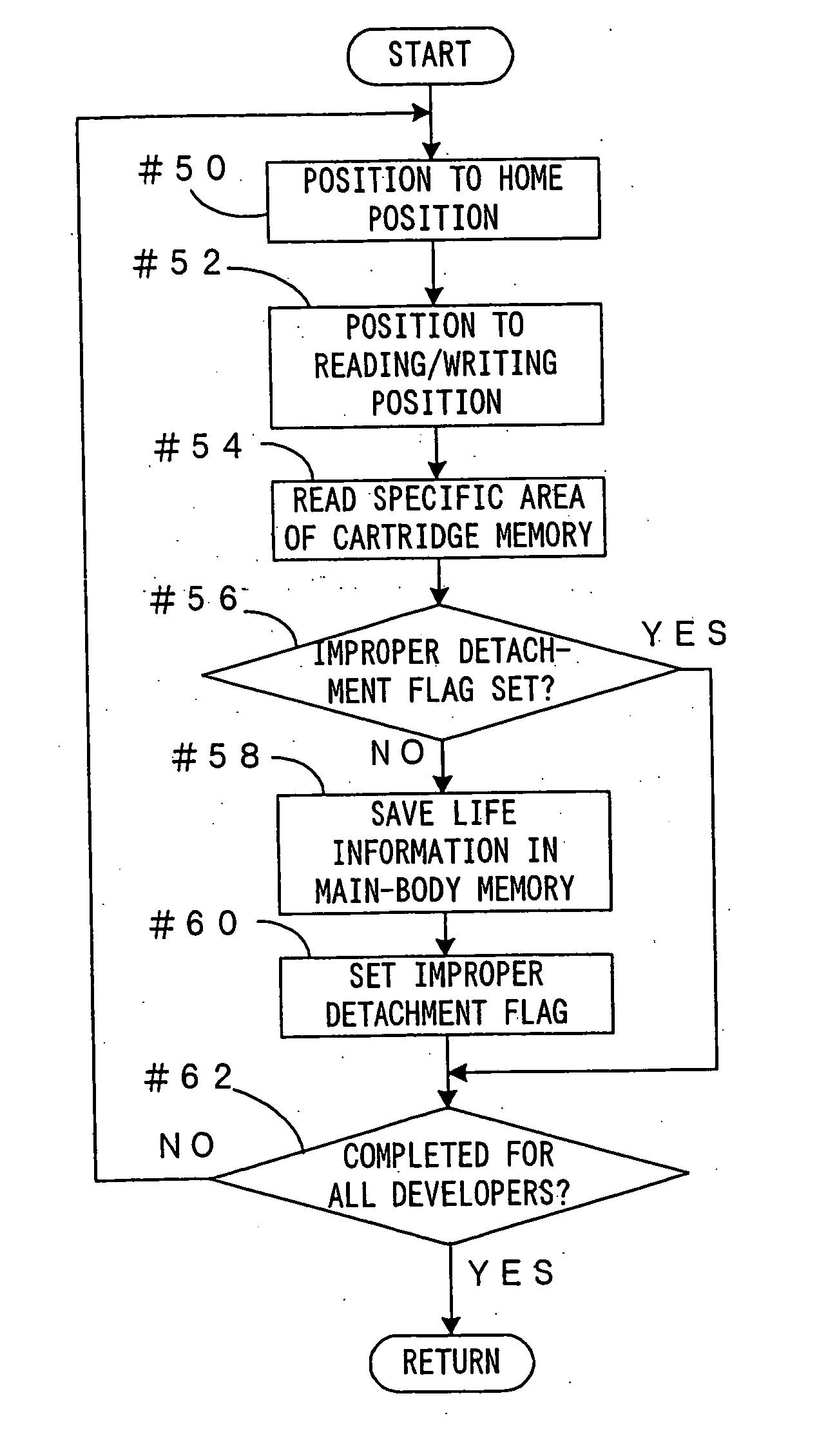
When an apparatus is turned on, one developer is positioned to a reading / writing position (Step #52) and a specific area of a cartridge memory is read (Step #54) to judge whether or not an improper detachment flag is set (Step #56). Unless the improper detachment flag is set (NO in Step #56), the improper detachment flag is set in the specific area of the cartridge memory (Step #60) after information on life saved in the cartridge memory is read and written in a main-body memory (Step #58).

Description

BACKGROUND OF THE INVENTION [0001] 1. Field of the Invention [0002] The invention relates to an image forming apparatus in which a cartridge storage means for saving intrinsic information including information on the life of a developer cartridge is provided in the developer cartridge constructed to be detachably mountable into an apparatus main body, and a storage controlling method for information on an improper detachment of the developer cartridge to be written in the cartridge storage means. [0003] 2. Description of the Related Art [0004] In printers, copiers, facsimile apparatuses and like image forming apparatuses for forming images using toner, a toner container is so constructed into a developer cartridge as to be detachably mountable into an apparatus main body, so that user can easily replenish the toner himself (for example, see Japanese Unexamined Patent Publication No. 2002-23595). In an apparatus disclosed in Japanese Unexamined Patent Publication No. 2002-23595, a de...

Claims


Application Information

Patent Timeline
Patent Type & Authority Applications(United States)
IPC IPC(8): G03G15/08G03G15/00
CPCG03G15/0822G03G2215/0177G03G15/0863G03G2221/1823G03G2215/0697
Inventor NAKAZATO, HIROSHI
Owner SEIKO EPSON CORP
Learn More