Image forming apparatus

Inactive Publication Date: 2006-09-21
S PRINTING SOLUTION CO LTD
View PDF7 Cites 16 Cited by
  • Summary
  • Abstract
  • Description
  • Claims
  • Application Information

AI Technical Summary

Benefits of technology

[0011] Aspects of the present invention solve the above and/or other drawbacks in the related art. An aspect of the invention provides

Problems solved by technology

However, at this point, in a case where a user does not correctly set the guide projections 5d to the guide rails 1b, the developing unit 5 c

Method used


Image

  • Image forming apparatus
  • Image forming apparatus
  • Image forming apparatus

Examples


Example

[0042] First Embodiment 1

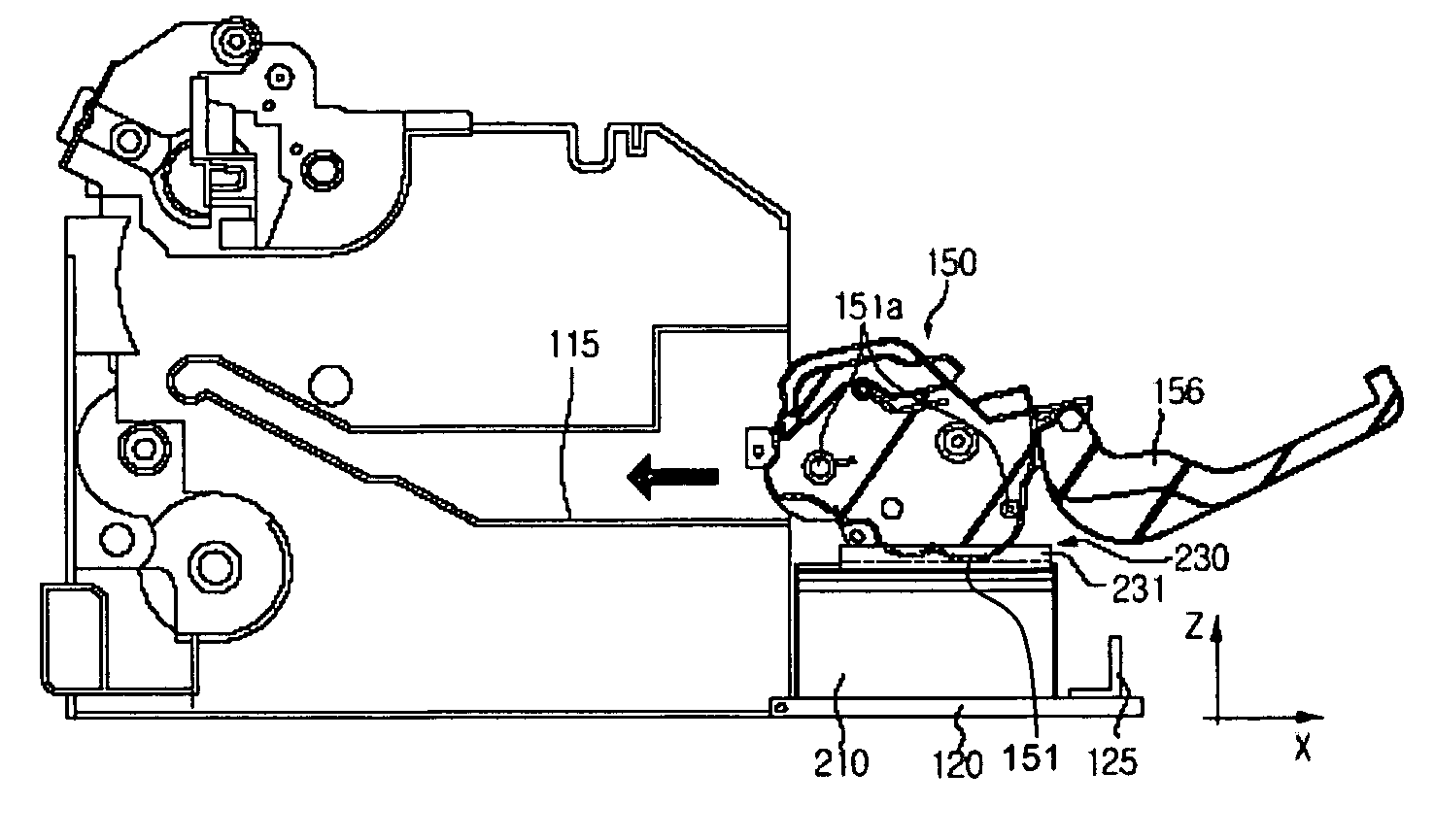
[0043]FIG. 5 is an elevational view showing an example of a guide unit of a developing unit formed on the recording medium cover of an image forming apparatus according to a first embodiment of the invention. As shown in FIG. 5, the guide projections 151 a are prominently formed at both sides of the cartridge 151 that forms the developing unit 150. The guide unit 230 to guide mounting operations of the developing unit 150 is provided on the top surface of the recording medium cover 210. The guide unit 230 comprises at least one guide rib 231 formed in a shape that corresponds to a shape of a bottom surface of the cartridge 151. The guide rib 231 is formed at both sides of the recording medium cover 210 and guides the cartridge 151 relatively stably. The shape of the guide rib 231 allows a portion of the guide rib 231 to be fitted into the bottom surface of the cartridge 151 so as to align the location of the developing unit 150. The guide rib 231 may compri...

Example

[0048] Second Embodiment

[0049] In the above description, an example of the guide unit 230 that is formed at the recording medium cover 210 is explained. However, the guide unit 230 may also be formed at the location of the recording medium width guide 127.

[0050]FIG. 7 is a vertical cross-sectional view showing a configuration of an image forming apparatus according to a second embodiment of the invention. The same symbols as those of FIG. 6 are used for the same portions as those of FIG. 6, and will not be explained in detail. As shown in FIG. 7, the difference from FIG. 6 is that the guide unit 250 is formed at the recording width guide 127.

[0051] The guide unit 250 is formed as a guide bar 251 that is installed at the recording medium width guide 127 to guide the movement of the developing unit 150. The guide bar 251 is installed so as to be elastically biased by an elastic member 253. That is, if the recording medium feed cover 120 is opened, the guide bar 251 protrudes outwar...


PUM


Abstract

Disclosed is an image forming apparatus in which a mount location of a developing unit being mounted on a main body of the apparatus is aligned in advance so that the developing unit smoothly enters the main body. For this purpose, a recording medium feed cover opens and closes the opening, the recording medium feed cover including a top surface on which the recording medium is stacked. A recording medium cover covers the recording medium stacked on the recording medium feed cover, and a guide unit, provided on the recording medium cover, guides a mounting location of the developing unit.

Description

CROSS-REFERENCE TO RELATED APPLICATION [0001] This application claims benefit under 35 U.S.C. § 119 from Korean Patent Application No. 2005-23089, filed on Mar. 21, 2005 in the Korean Intellectual Property Office, the disclosure of which is incorporated herein by reference. BACKGROUND OF THE INVENTION [0002] 1. Field of the Invention [0003] An aspect of the present invention relates to an image forming apparatus, and, more specifically, the invention relates to an image forming apparatus on which a developing unit may be relatively easily mounted. [0004] 2. Description of the Related Art [0005] Generally, an electro-photographic image forming apparatus, such as a laser beam printer, is an apparatus that forms an electrostatic latent image on a photosensitive medium such as a photosensitive drum or a photosensitive belt, and obtains a desired image by developing the electrostatic latent image with a certain colored developer and transcribing that electrostatic latent image onto a rec...

Claims


Application Information

Patent Timeline
IPC IPC(8): G03G21/18
CPCG03G21/16G03G2221/163G03G2221/1672G03G21/1638G03G21/1676G03G21/185G03G15/6502G03G2215/00383
Inventor SONG, GWAN-SEOB
Owner S PRINTING SOLUTION CO LTD
Why Eureka
Try Eureka