Wellbore communication system

a communication system and wellbore technology, applied in the field of subterranean formation exploration/production, can solve the problems of limited depth capability and require more expertise to opera

Inactive Publication Date: 2006-09-28
SCHLUMBERGER TECH CORP
View PDF18 Cites 30 Cited by
  • Summary
  • Abstract
  • Description
  • Claims
  • Application Information

AI Technical Summary

Problems solved by technology

For example, electromagnetic telemetry is simple to set up and operate, but can be dependent on formation characteristics and have limited depth capability.
In other cases, mud pulse telemetry tools may be capable of extreme depths, but may be sensitive to the mud conditions and require more expertise to operate.
Existing telemetry tools are typically housed in an expensive drill collar, designed specifically to couple with the telemetry tool.

Method used


Image

  • Wellbore communication system
  • Wellbore communication system
  • Wellbore communication system

Examples


Embodiment Construction

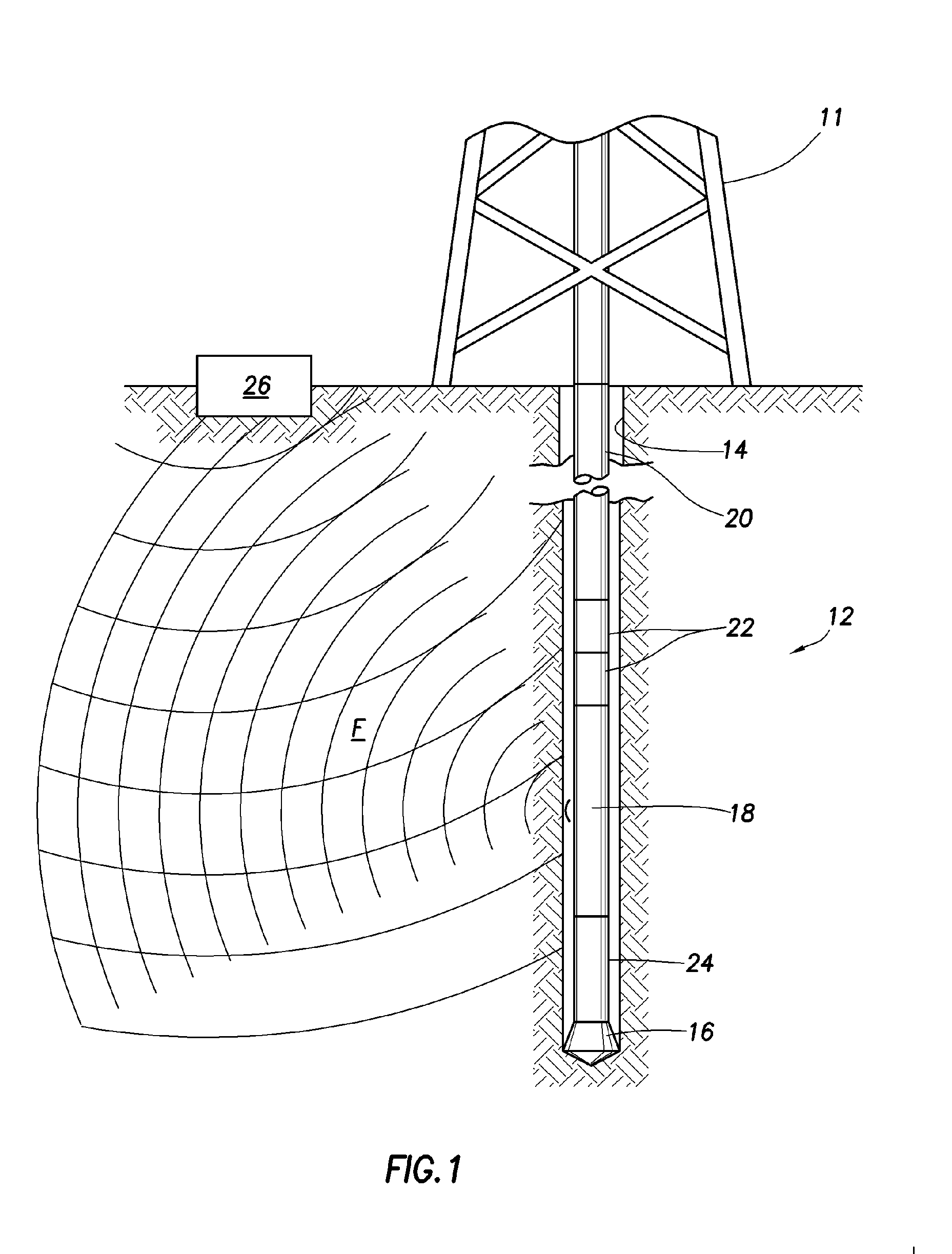
[0021] Referring now to FIG. 1, a rig 11 supports a downhole drilling tool 12 that is suspended from the rig 11 in a wellbore 14. The downhole tool 12 is adapted to drill the wellbore 14 using a drill bit 16 located at a lower end thereof. The downhole tool 12 is operatively connected to and includes a downhole telemetry tool 18 and a drill string 20. The drill string 20 includes a plurality of drill collars connected to form the drill string 20.

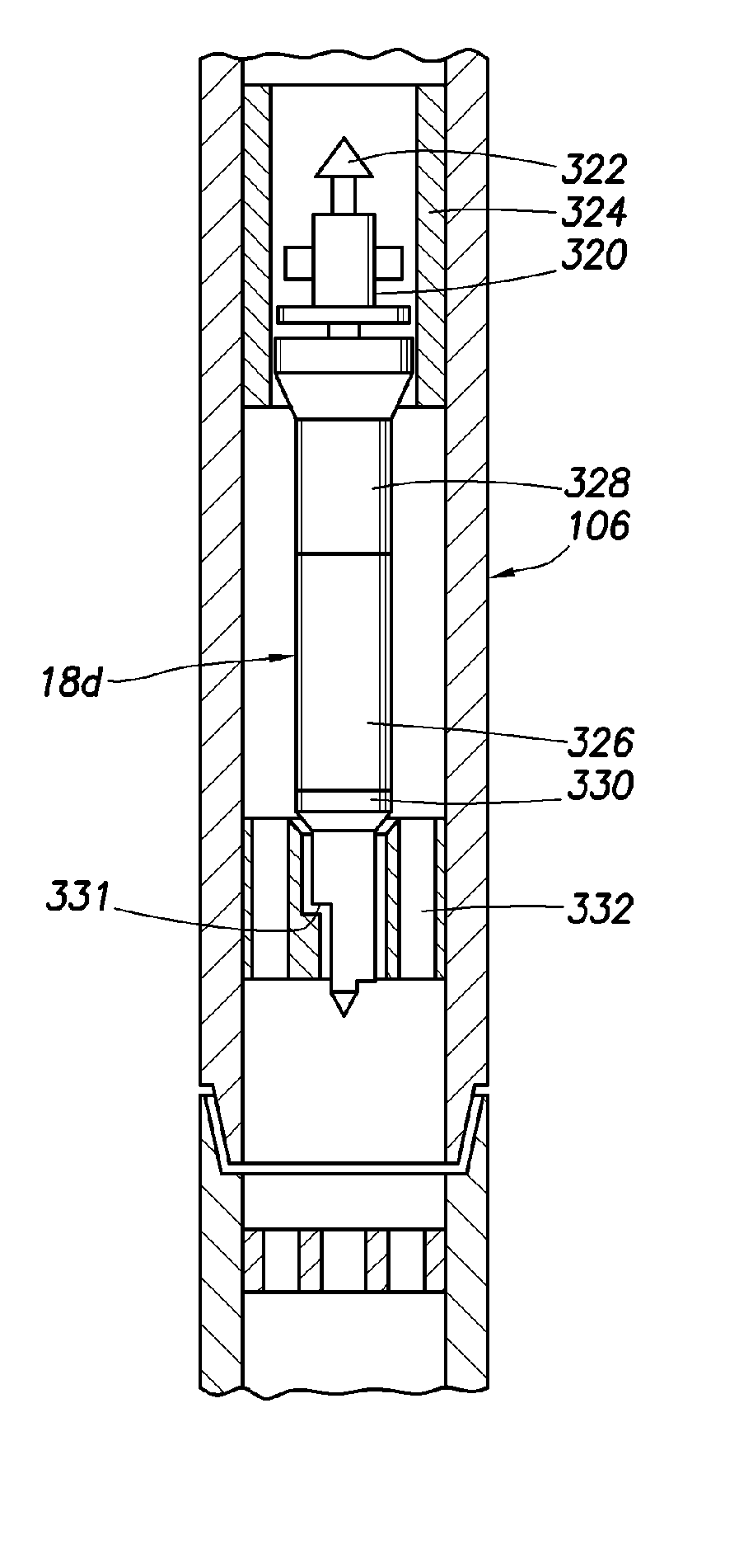
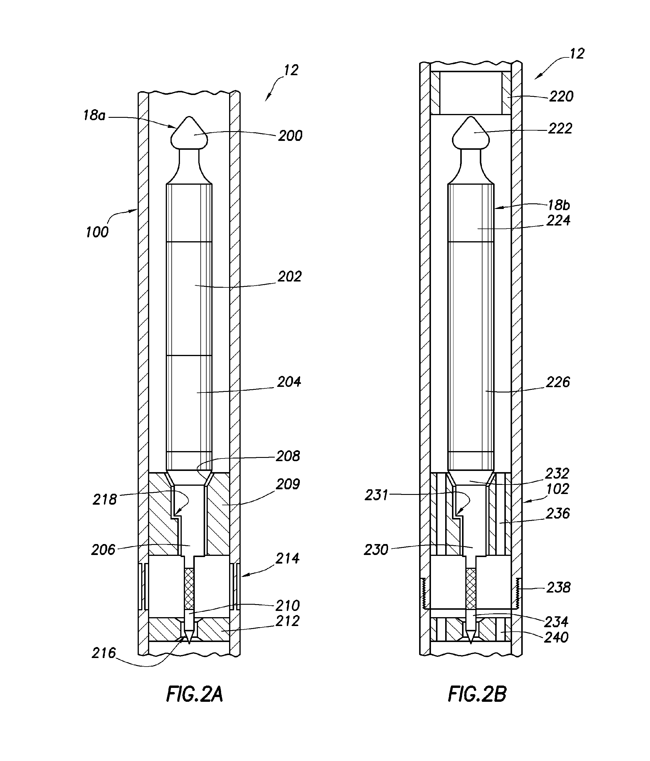
[0022] Various components, such as the telemetry tool 18, sensors 22, a power unit 24, as well as other components, are positioned in one or more drill collars and enable the downhole tool 12 to perform various downhole operations. The telemetry tool 18 may be an electromagnetic tool, as further described with respect to FIGS. 2A and 2B, that communicates with a surface detection unit 26 capable of detecting electromagnetic pulses, or a mud pulse tool, as further described with respect to FIGS. 3A and 3B, that communicates with a surface de...


PUM


Abstract

A telemetry system for a downhole tool positionable in a wellbore penetrating a subterranean formation is provided. The telemetry system includes a telemetry tool engageable within the downhole tool. The telemetry tool including a telemetry unit, the unit being interchangeable between a mud pulse telemetry unit and an electromagnetic telemetry unit.

Description

CROSS-REFERENCES [0001] The present application claims priority of U.S. Provisional Patent Application Ser. No. 60 / 594,273 filed on Mar. 24, 2005. The Provisional Application is incorporated by reference in its entirety.BACKGROUND OF THE INVENTION [0002] The present invention relates to the exploration / production of a subterranean formation penetrated by a wellbore. More particularly, the present invention relates to techniques for communicating between equipment at the surface, and a downhole tool positioned in the wellbore. [0003] The exploration and production of hydrocarbons involves placement of a downhole tool into the wellbore to perform various downhole operations. There are many types of downhole tools used in hydrocarbon reservoir exploration / production. Typically, a drilling tool is suspended from an oil rig and advanced into the earth to form the wellbore. The drilling tool may be a measurement-while-drilling (MWD) or a logging-while-drilling (LWD) tool adapted to perfor...

Claims


Application Information

Patent Timeline
Patent Type & Authority Applications(United States)
IPC IPC(8): G01V3/00
CPCE21B47/12
Inventor PRINGNITZ, STEVEN J.BOLING, BRIAN E.THORP, RICHARD E.
Owner SCHLUMBERGER TECH CORP
Why Eureka
Try Eureka