
Floating protection barrier gate

a floating protection and gate technology, applied in water cleaning, construction, weapons, etc., can solve the problems of low protection or durability of conventional grp port security barrier modules, high maintenance costs, and inability to meet the needs of us

Inactive Publication Date: 2006-09-28
INNOVATION TECH APPL
View PDF22 Cites 21 Cited by
  • Summary
  • Abstract
  • Description
  • Claims
  • Application Information

AI Technical Summary

Problems solved by technology

While the use of GRP for components of a harbor protection barrier is an improvement over the use of a mostly-steel or an all-steel construction for a harbor protection barrier in some respects (e.g., lower maintenance costs), it still has problems associated with not being as structurally strong as the mostly-steel construction, and thereby it does not provide as good a protection or durability as one would get from the mostly-steel construction or all-steel construction of a harbor protection barrier.
One can surmise from that test that boats following a lead boat (which impacted the GRP protection barrier) may be able to follow the same path in the water as the lead boat and thereby penetrate into a region protected by one or more GRP protection barriers, which is clearly undesirable.
Furthermore, conventional GRP Port Security barrier modules are not particularly sturdy with respect to dealing with forces due to boat attacks and / or forces due to severe weather conditions.
Also, for an all-steel construction or for a mostly-steel construction of a Port Security barrier, there is a problem in that maintenance costs are very high.
For example, when the Port Security barrier is floating in the water, it deteriorates over time due to the sea water that comes in contact with the steel.
This leads to rusting, which causes deterioration of the Port Security barrier, thereby making it less structurally sound.
While such steel-constructed Port Security barriers typically have a paint coat to partially counter the rusting problem, the conventional Port Security barriers have to be painted fairly often in order to maintain the structural integrity of the paint barrier, which again results in high maintenance costs.
Furthermore, with conventional Port Security barriers, there is a problem associated with coupling two or more harbor protection barrier modules together to protect a large region, such as a harbor.
This loose coupling results in undesired stresses being imparted to individual protection barrier modules as they flop around in the water due to inclement weather conditions such as high wave and high wind conditions.
Such a loose coupling between protection barrier modules may result in damage to individual protection barrier modules, with results in an undesired cost associated with repairing protection barrier modules already installed or having to utilize new protection barrier modules to replace protection barrier modules that are damaged beyond repair.
There is also a problem with respect to providing ‘gates’ for allowing friendly boats into a protected area.
Current protection barrier structures do not provide for such gates, thereby making it difficult for friendly boats to pass into and out of protected water areas.

Method used


Image

  • Floating protection barrier gate
  • Floating protection barrier gate
  • Floating protection barrier gate

Examples


first embodiment

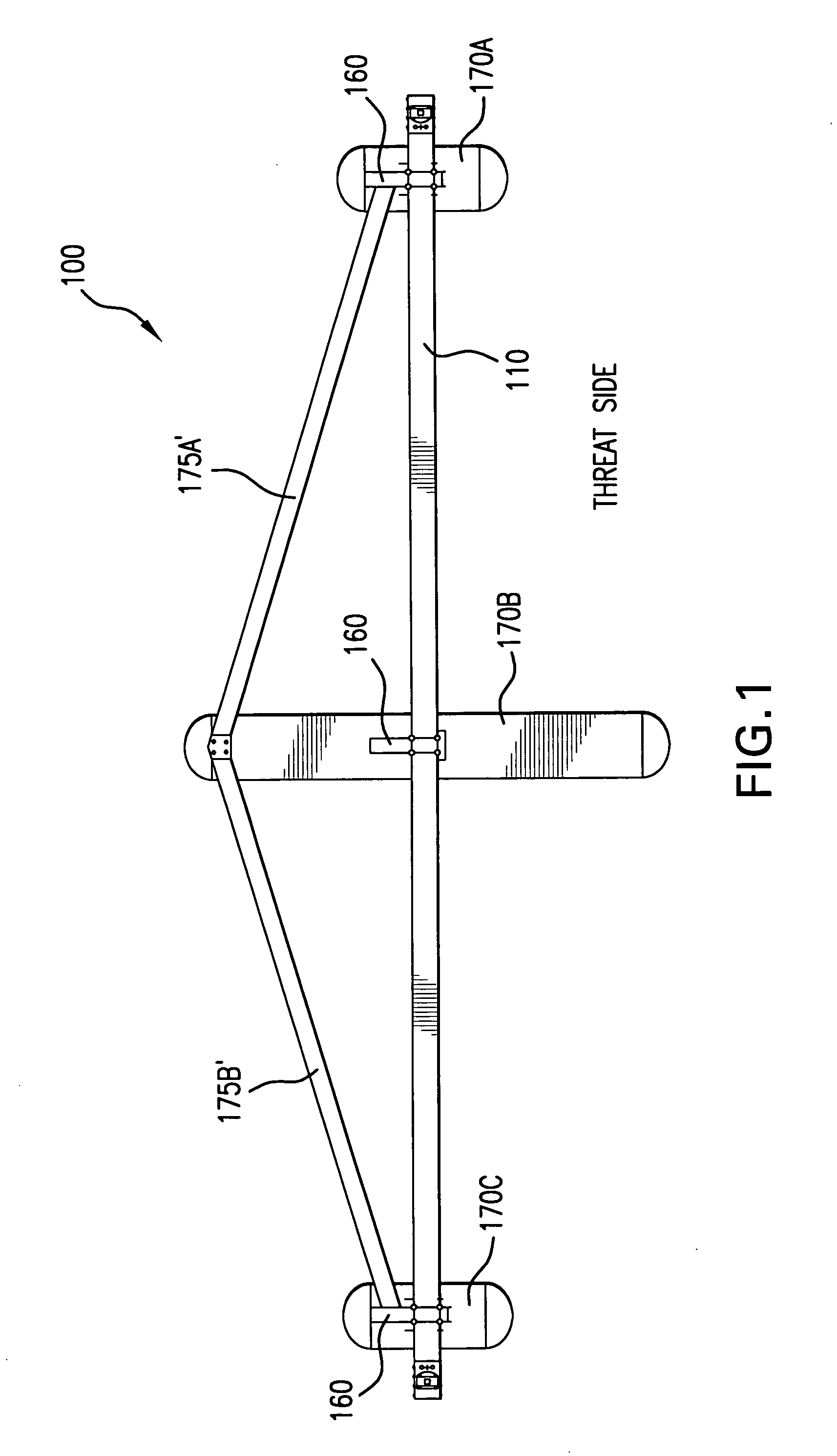
[0024] The HPB is very similar to the HPB as described in U.S. patent application Ser. No. 10 / 621,655, entitled “Protection Barrier Apparatus”, which is assigned to the same assignee as this application, and which is incorporated in its entirety herein by reference.

[0025] The HPB according to the first embodiment is fabricated out of composite materials for practically all of the portion of the protection barrier structure that is disposed above the water line, and it is constructed primarily out of foam materials for the pontoon structure that floats on the water and that provides the structural capability for each HPB protection barrier unit to float on the water. The HPB is designed to have a low life cycle maintenance cost as compared to conventional structures, while at the same time it is designed to provide an acceptable boat stopping capability to protect military and / or commercial harbors or other types of regions that abut a body of water (or to protect a water region or ...

second embodiment

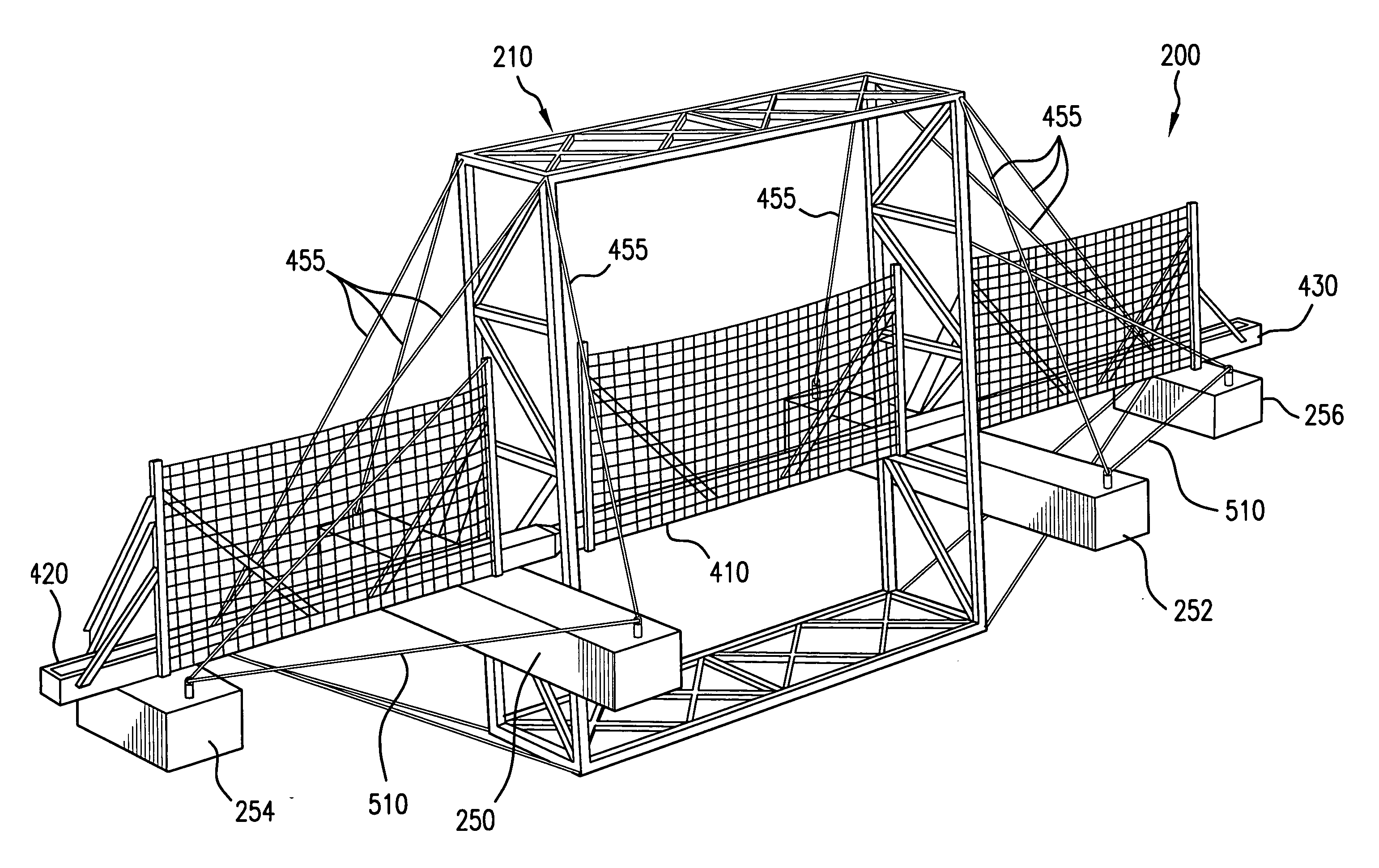
[0029] the invention will be described below with reference to FIGS. 2-6, which show various features of a gate barrier 200 that includes a truss 210. The gate barrier 200 may be utilized with non-gate barriers to provide protection over a large region, whereby the non-gate barriers may be constructed as described above with respect to the first embodiment or as described in the various embodiments provided in the co-pending U.S. patent application Ser. No. 10 / 621,651, or whereby the non-gate barriers may be any conventional harbor protection barrier.

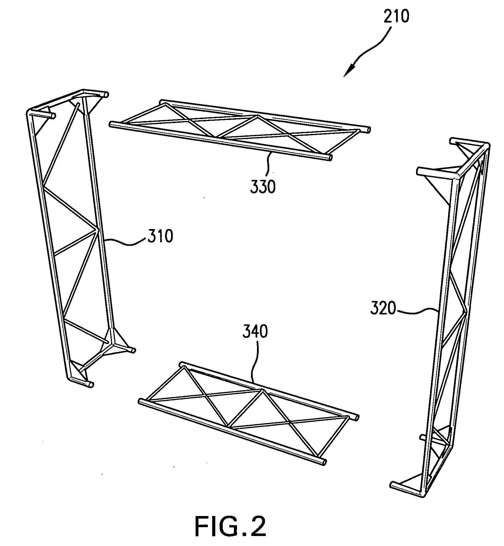
[0030] The gate barrier 200 includes a truss structure 210, as shown in FIGS. 2 and 3. The truss structure 210 includes two vertical truss sections 310, 320 and two horizontal truss sections 330, 340, which are connected together to form a box-like structure (see FIG. 3). The truss sections are preferably made of stainless steel pipe, such as Schedule 40 steel, or carbon steel. Preferably, 3″ Schedule 40 pipes are used for the main trus...

third embodiment

[0051] In a third embodiment, the gate 410 may be configured to open straight upward (vertically) instead of straight across (horizontally), whereby a wire rope / pulley mechanism that is coupled to the gate and to the top horizontal portion 330 of the truss 210 may be utilized to achieve such movement of the gate 410.


PUM


Abstract

A protection apparatus protects a harbor or an area in a body of water or adjacent to a body of water. The protection apparatus floats on the body of water, and includes a plurality of barrier units positioned side-by-side, each of the barrier units includes a composite-based durable barrier structure. The barrier structure is configured to hold a net in place in order to protect an area in the body of water or abutting the body of water from waterborne craft. At least one of the barrier units includes a gate that allows passage of waterborne craft into and out of the protected body of water.

Description

BACKGROUND OF THE INVENTION [0001] A. Field of the Invention [0002] The invention relates generally to protection barriers and, more particularly, to durable, floating boat barriers that are used to protect areas such as harbors, water regions, or other types of land or water areas from high speed and low speed water craft attack. [0003] B. Description of the Related Art [0004] In the current environment with terrorist activities on the rise, there is a need to protect assets from terrorist attacks. One type of protection device is a floating harbor protection barrier system designed to provide protection to military and commercial harbors from high speed surface boat attacks. [0005] Initial research into harbor protection by the Naval Facilities Engineering Service Center led to the development of a mostly mild-steel structure called the Port Security Barrier. The Port Security Barrier consists of three steel pontoons supporting a steel box beam, steel supports for netting, steel b...

Claims


Application Information

Patent Timeline
IPC IPC(8): E02B15/04
CPCF41H11/05
Inventor BAKER, MICHAEL K.LISSE, STEPHEN D.PACHECO, CHRISTOPHER P.WHITMAN, CLARK E.
Owner INNOVATION TECH APPL
Learn More