
Method for characterizing biological indicators n sterilization processes and apparatus for the implementation thereof

a technology of biological indicators and sterilization processes, applied in biochemistry apparatuses, biochemistry apparatuses and processes, flexible elements, etc., can solve the problems of not being able to ensure the actual sterilization, the minimum physical sterilization parameters of the sensors, and the cases

Active Publication Date: 2006-09-28
FEDEGARI AUTOCLAVI
View PDF2 Cites 2 Cited by
  • Summary
  • Abstract
  • Description
  • Claims
  • Application Information

AI Technical Summary

Benefits of technology

[0011] However, while the determination of N0 is within the competence of any microbiologist, the determination of D and z is anything but easy and require methods which are laborious and produce non-repetitive results.

Problems solved by technology

The detection of the minimum physical sterilization parameters by the sensors may, in some cases, not be sufficient to ensure the actual sterilization of the product; in fact both the position of the sensors, and the type of physical parameter detected, always provide indirect or incomplete information as to the overall performance of the process.

Method used


Image

  • Method for characterizing biological indicators n sterilization processes and apparatus for the implementation thereof
  • Method for characterizing biological indicators n sterilization processes and apparatus for the implementation thereof
  • Method for characterizing biological indicators n sterilization processes and apparatus for the implementation thereof

Examples


Embodiment Construction

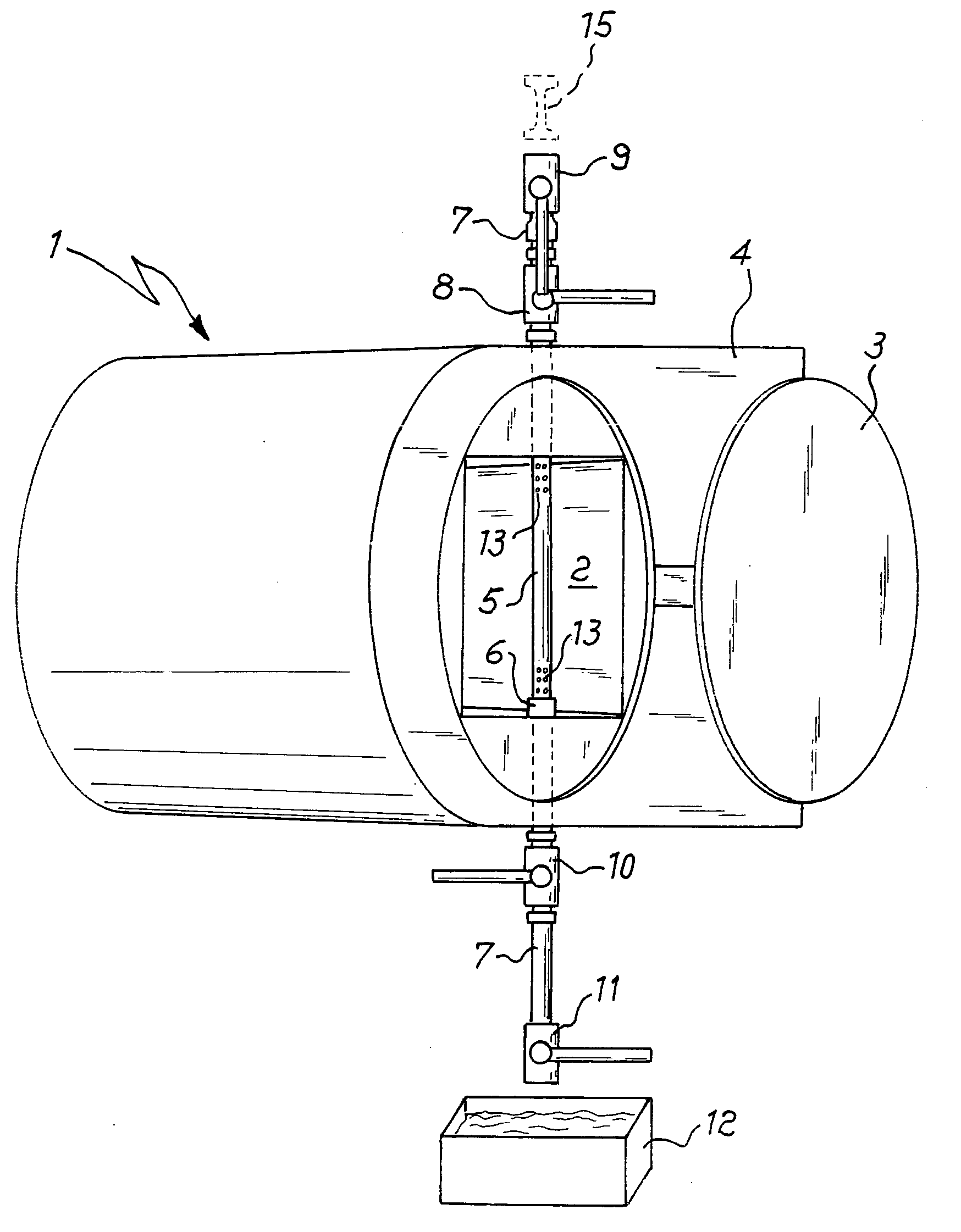
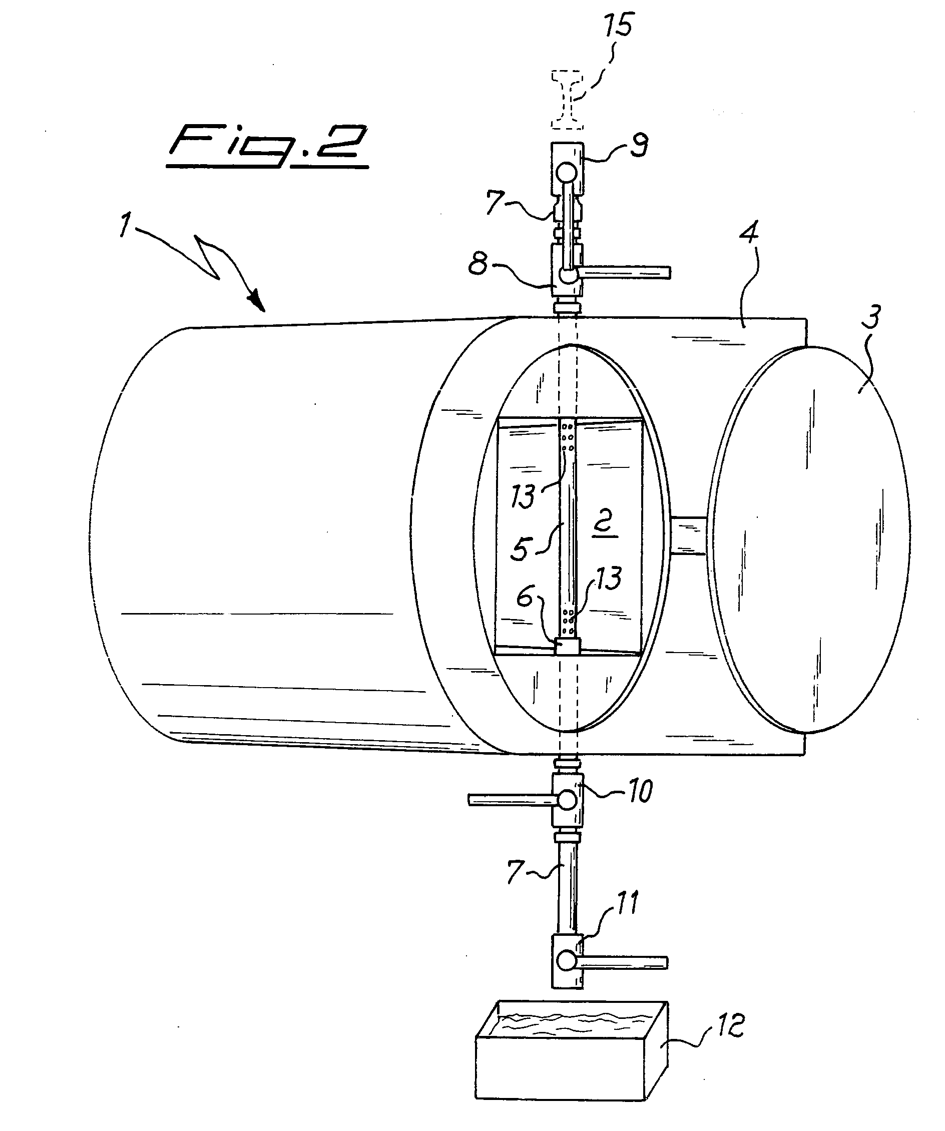
[0032] In the figures, 1 denotes overall a sterilizer in accordance with the invention, which comprises a sterilization chamber 2 inside which the objects to be treated are deposited.

[0033] During use, the chamber 2 is sealed hermetically by a hatch 3 and the steam is supplied inside it in a known manner: for this purpose, in this case, the body 4 of the sterilizer, i.e. its part comprising the wall which encloses the chamber 2 and incorporates the various means for forming and / or supplying the steam, is constructed in a manner known per se, as for example in the sterilizers produced and marketed by the applicants of the present application.

[0034] As can be seen, the sterilization chamber 2 is of the horizontal-axis type and is passed through vertically by a duct 5 consisting of a tube screwed at the bottom onto a threaded union 6 on the bottom of the chamber; at the top the duct 5 passes through the wall of the sterilizer and at its end sealingly engages, in a manner known per se...


PUM

PropertyMeasurementUnit
Timeaaaaaaaaaa
Biological propertiesaaaaaaaaaa
Gravityaaaaaaaaaa

Abstract

The invention relates to a method for characterizing the bioindicators in sterilization processes using an autoclave and the like, in which a bioindicator is kept in the same conditions as the sterilization chamber (2) and extracted after a predetermined time interval. For this purpose the chamber (2) has, passing through it, a tube (5) on the ends of which valves (8-9, 10-11) are mounted, said valves allowing the insertion, from above, of a bioindicator sample and its extraction from below, when required, without a significant loss of sterilizing agent. Alternatively, the duct (5) may also be arranged outside the sterilization chamber (2) and kept in communication therewith by a bypass connection.

Description

RELATED APPLICATIONS [0001] This application claims priority to Italian Patent Application No. MI2005A000506 filed Mar. 24, 2005, the teachings of which are incorporated herein by reference. BACKGROUND OF THE INVENTION [0002] The invention relates in general to the monitoring of sterilization processes in the pharmaceutical, food, sanitary and similar fields. SUMMARY OF THE INVENTION [0003] As is known, an important aspect of the sterilization processes is monitoring of the total destruction or the degree of reduction in the microbic content of the product undergoing treatment. [0004] Typically, said monitoring is performed using two methods which are employed alternately and are also applicable in parallel. [0005] The first method is of the physical type (measurement of physical parameters such as temperature, pressure, concentration of the sterilizing agent) and in the case of wet heat processes (such as, for example, saturated steam processes) aims to ensure that the coldest poin...

Claims


Application Information

Patent Timeline
IPC IPC(8): G01N33/00
CPCA61L2/06A61L2/07A61L2/202A61L2/206A61L2/208A61L2/28A61L2202/122A61L2202/21B29C65/56B29C66/69B65D63/12
Inventor FEDEGARI, FORTUNATO
Owner FEDEGARI AUTOCLAVI
Learn More