
Cage of a roller bearing and method for producing such a cage

a cage and roller bearing technology, applied in the field of cages of roller bearings, can solve the problems of increasing production time and cost, unable to be removed, and the raw material cost is higher than necessary with respect to the required strength of the cage, so as to reduce the amount of raw materials, and reduce the potential raw material cost

Active Publication Date: 2018-08-14
AB SKF
View PDF7 Cites 0 Cited by
  • Summary
  • Abstract
  • Description
  • Claims
  • Application Information

AI Technical Summary

Benefits of technology

The patent text discusses the use of metal cages, which have several benefits. Firstly, metal cages provide stronger materials that can withstand higher levels of material removal, making them better suited for applications like cutting and milling. Secondly, metal cages can be easily produced using 3D printing technology, which is cost-efficient and allows for greater accuracy. Thirdly, metal cages are often lighter than traditional cages, which means they can be designed to be more flexible and adaptable to changes in acceleration and deceleration. Lastly, metal cages have lower inertia, which means they can better adjust to misalignment and high levels of acceleration and deceleration.

Problems solved by technology

This classical production technology means however, that any additional removal of material which is not needed for the strength of the cage (for example to reduce weight) increases production time and cost.
If the material is at a location which cannot be reached by a turning or milling tool, it cannot be removed.
Despite the fact that this material is not needed and removed later it must still be paid for and thus causes cost.
Hence the raw material cost is higher than necessary with respect to the required strength of the cage.

Method used


Image

  • Cage of a roller bearing and method for producing such a cage
  • Cage of a roller bearing and method for producing such a cage
  • Cage of a roller bearing and method for producing such a cage

Examples


Embodiment Construction

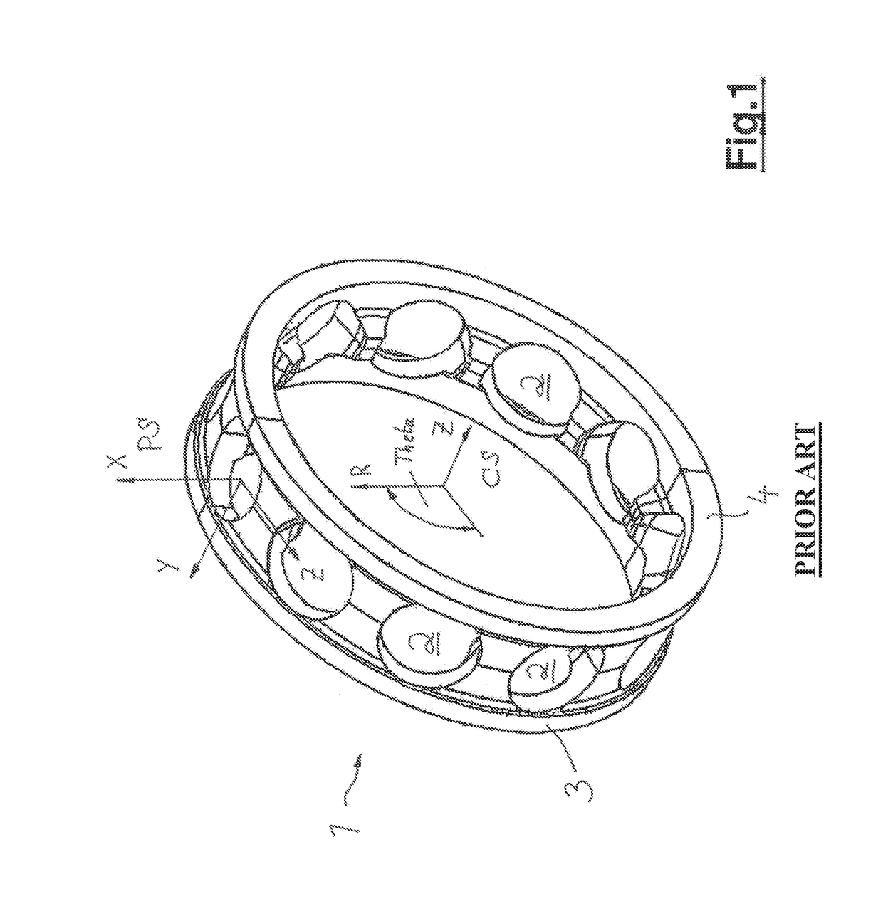
[0044]In FIG. 1 a cage 1 according to the state of the art is shown with a basis geometry which is hollow-cylindrical. The cage 1 has a plurality of pockets 2 for receiving rolling elements; the pockets 2 form surfaces for contacting the rolling element (which are not depicted). The cage 1 is thus composed of multiple pockets, each pocket providing the space for a rolling element.

[0045]In FIG. 1 the coordinate systems are depicted which are used for the further explanation of the design of the cage according to the invention. For the definition, two coordinate systems are used.

[0046]A global cylindrical coordinate system CS (cage system) is defined with the radial direction R being normal to the outer ring outer surface of the bearing and the axial direction z being the middle axis of the bore of the bearing.

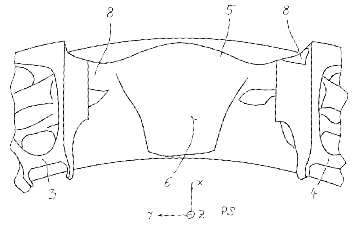
[0047]A Cartesian coordinate system PS (pocket system) is placed at the center of the rolling element, with the x direction pointing in insertion direction of the rolling elemen...


PUM


Abstract

A cage for a roller bearing is provided. The cage has a ring-shaped base body with a plurality of pockets for receiving rolling elements. The base body is formed by two side rings arranged in a defined axial distance and by a plurality of pocket elements, which are located between the side rings. Each pocket element has two face sides designed for contacting a rolling element. The connection between the pocket element and each of the side rings is established by at least one beam joined with one of the side rings and the pocket element. The beam is a positive substance joined with one of the side rings and the pocket element and has a ring-shaped or elliptical cross section in a section perpendicular to the longitudinal extension of the beam.

Description

CROSS REFERENCE TO RELATED APPLICATIONS[0001]This is a United States National Stage Application claiming the benefit of International Application Number PCT / EP2015 / 064695 filed on Jun. 29, 2015 which claims the benefit of British Patent Application 1411890.5 filed on 7 Mar. 2014, both of which are incorporated herein by reference in their entireties.FIELD OF THE INVENTION[0002]The invention relates to a cage of a roller bearing, wherein the cage has a basically ring-shaped base body with a plurality of pockets for receiving of rolling elements. Furthermore, the invention relates to a method for producing such a cage.BACKGROUND OF THE INVENTION[0003]Cages of roller bearings are usually rotationally symmetric components that are normally made by stamping or injection molding for medium and high production volumes and by turning and milling for low volume production or if high strength and / or special materials are required. In the latter case, manufacturing starts typically with a tube...

Claims


Application Information

Patent Timeline
Patent Type & Authority Patents(United States)
IPC IPC(8): F16C33/38F16C33/46
CPCF16C33/38F16C33/385F16C33/46F16C33/3843F16C33/3887F16C33/3806F16C33/4676F16C33/4623F16C19/06F16C2326/43F16C2240/70F16C33/3862F16C33/3875F16C33/4617F16C33/4641F16C33/4652
Inventor KREBS, PHILIPPPETERS, GILBERTZIEGLER, SEBASTIANZIMMERMAN, GREGORY A
Owner AB SKF
Learn More