Leadscrew assembly with a wire-wound leadscrew and a spring-pin engagement of a drive nut to the leadscrew

a technology of leadscrew and wire-wound, which is applied in the direction of gearing, gearing elements, hoisting equipment, etc., can solve the problems of excessive thread wear of the conventional leadscrew assembly, limited to relatively large-size devices and coarse thread pitches, and relatively expensive production of conventional leadscrew assemblies. , to achieve the effect of avoiding backlash and being inexpensive to produ

Active Publication Date: 2008-03-04
RAYTHEON CANADA LTD
View PDF14 Cites 11 Cited by
  • Summary
  • Abstract
  • Description
  • Claims
  • Application Information

AI Technical Summary

Benefits of technology

[0006]The present invention provides a leadscrew assembly that is particularly suitable for light-duty applications wherein the loads and speeds of movement are small to moderate in magnitude. It is tolerant of misalignments and is preloaded to avoi

Problems solved by technology

This conventional leadscrew assembly is relatively expensive to produce due to the precision machining required.
It is also limited to relatively large-size devices and coarse thread pitches because of the size of the balls used in the recirculating ball nut structure.
The conventional leadsc

Method used


Image

  • Leadscrew assembly with a wire-wound leadscrew and a spring-pin engagement of a drive nut to the leadscrew
  • Leadscrew assembly with a wire-wound leadscrew and a spring-pin engagement of a drive nut to the leadscrew
  • Leadscrew assembly with a wire-wound leadscrew and a spring-pin engagement of a drive nut to the leadscrew

Examples


Embodiment Construction

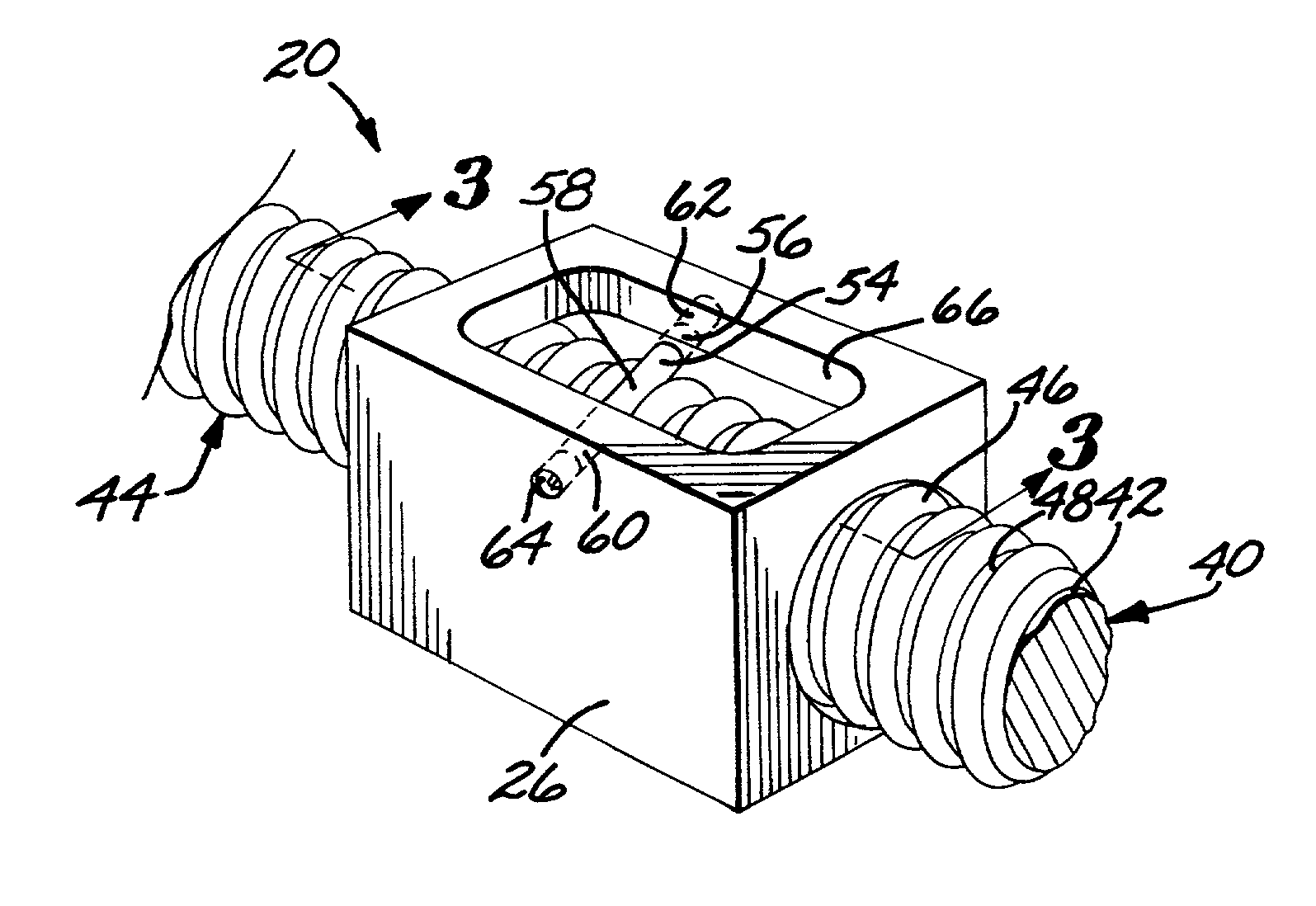
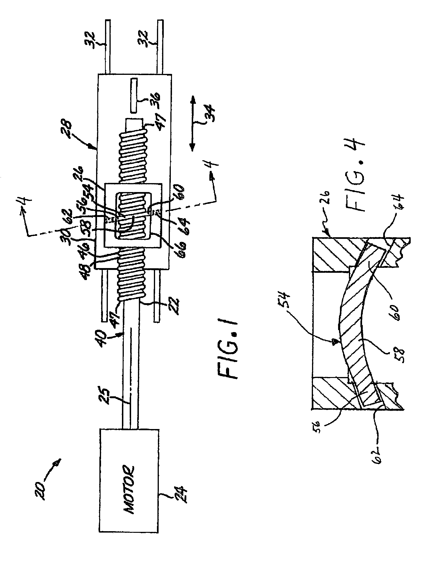
[0017]FIG. 1 depicts a leadscrew assembly 20 including a leadscrew 22 driven by a motor 24, such as a miniature stepper motor, having a rotational power output about a rotational axis 25. The leadscrew 22 engages a hollow drive nut housing 26 that is affixed to a linear slide mechanism 28 so that the drive nut housing 26 does not rotate. The linear slide mechanism 28 includes a slider 30 mounted on rails 32 to move linearly parallel to a linear movement direction 34. A supported object, in the illustrated case an optical filter 36, is supported on the slider 30. Rotary motion of the power output of the motor 24 introduced into the leadscrew 22 is thereby translated into a linear movement of the optical filter 36 parallel to the linear movement direction 34.

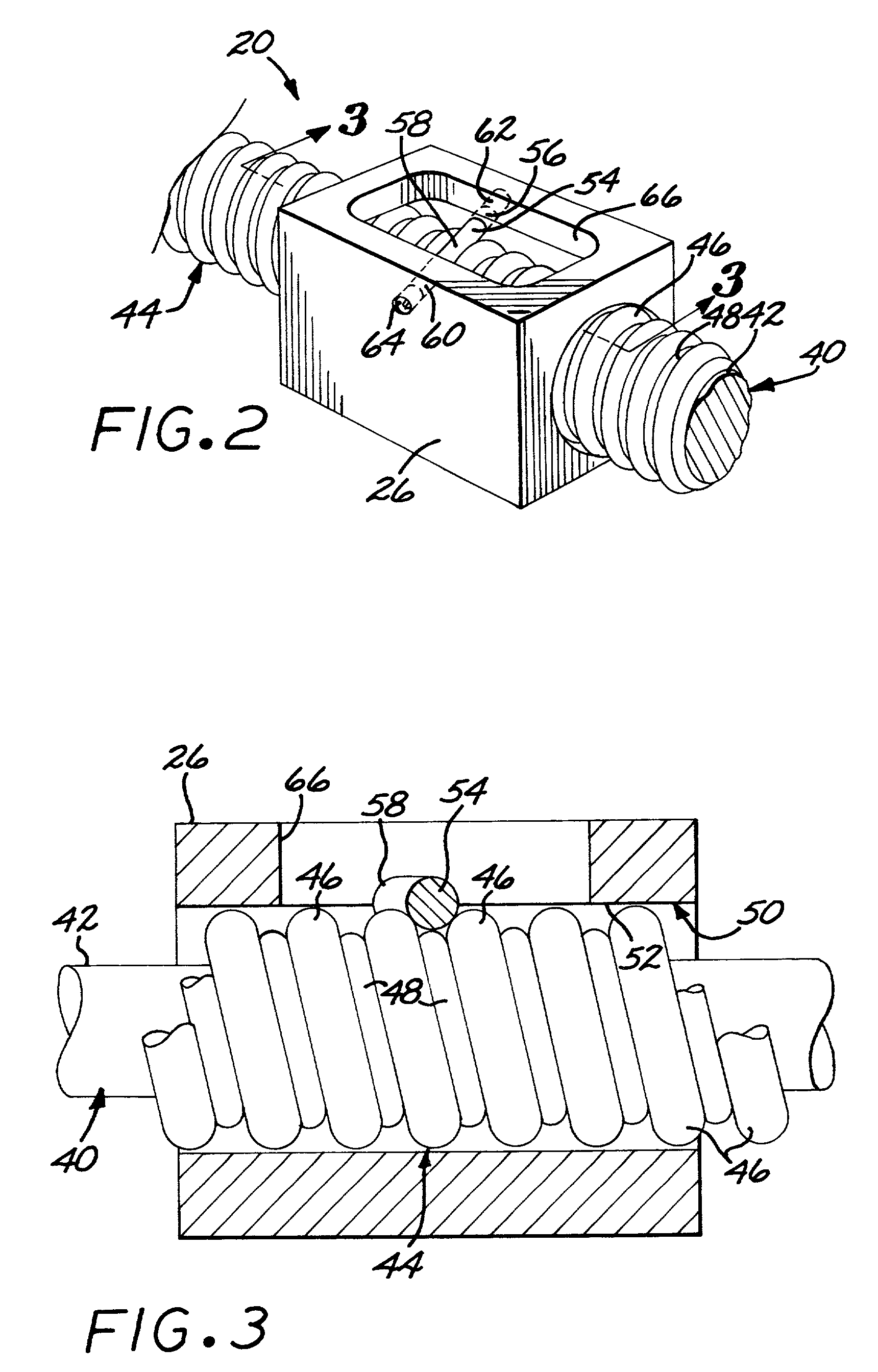
[0018]FIGS. 2-3 illustrates the leadscrew 22 and drive nut housing 26 in greater detail. The leadscrew 22 comprises an elongated shaft 40 having an outer lateral surface 42 and the rotational axis 25. The shaft 40 is preferably cy...


PUM


Abstract

A leadscrew assembly includes a leadscrew having an elongated shaft with an outer lateral surface and a rotational axis, and a leadscrew thread formed of a thread wire helically wrapped in spaced-apart turns upon the lateral surface and affixed to the elongated shaft. A hollow drive nut housing includes a nut bore having an unthreaded inner surface. The leadscrew is inserted through the nut bore. The nut bore is sized such that the leadscrew may rotate therein about the rotational axis. A spring pin is affixed to the drive nut housing and spans across the nut bore to engage the leadscrew thread.

Description

BACKGROUND OF THE INVENTION[0001]This invention relates to a mechanical movement to translate rotational to linear motion and, more particularly, to an inexpensive leadscrew linear-movement assembly.[0002]Electric motors commonly produce a rotational output, but many mechanisms require a linear movement driven by the motor. A leadscrew assembly is one approach for translating the rotational movement of the motor to the required linear movement. In the conventional leadscrew assembly, the thread of an externally threaded leadscrew engages a recirculating ball nut structure, which in turn is engaged to the structure to be driven linearly. As the leadscrew turns, the ball nut structure and the driven structure move linearly.[0003]This conventional leadscrew assembly is relatively expensive to produce due to the precision machining required. It is also limited to relatively large-size devices and coarse thread pitches because of the size of the balls used in the recirculating ball nut s...

Claims


Application Information

Patent Timeline
IPC IPC(8): F16H1/24F16H55/02F16H25/24
CPCF16H25/2427Y10T74/1973
Inventor DEVENYI, GABOR
Owner RAYTHEON CANADA LTD
Why Eureka
Try Eureka