Apparatus for rotating aligning a substrate

A technology for aligning devices and substrates, which is applied in the manufacture of electrical components, electrical solid devices, semiconductor/solid devices, etc., can solve the problems of lower precision and lower deposition quality, and achieve the effect of preventing reversal phenomenon

Inactive Publication Date: 2016-05-04
SNU PRECISION CO LTD
View PDF7 Cites 4 Cited by
  • Summary
  • Abstract
  • Description
  • Claims
  • Application Information

AI Technical Summary

Problems solved by technology

This reduces accuracy in deposition devices that require precise alignment of mas

Method used


Image

  • Apparatus for rotating aligning a substrate
  • Apparatus for rotating aligning a substrate
  • Apparatus for rotating aligning a substrate

Examples


Embodiment Construction

[0030] Hereinafter, a substrate rotational alignment device according to an embodiment of the present invention will be described in detail with reference to the accompanying drawings.

[0031] A substrate rotation alignment device according to an embodiment of the present invention relates to a phenomenon in which a rotation axis is prevented from being twisted by a pressing force when a mounting part on which a substrate is mounted is rotated to align a substrate on a mask, thereby Rotary alignment device for substrates capable of precise alignment.

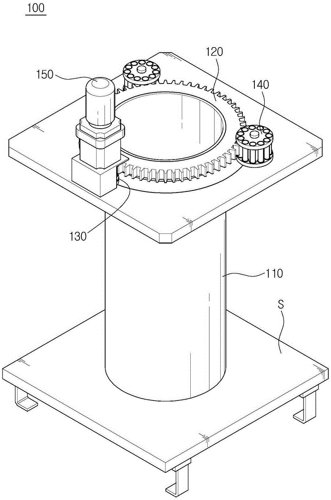
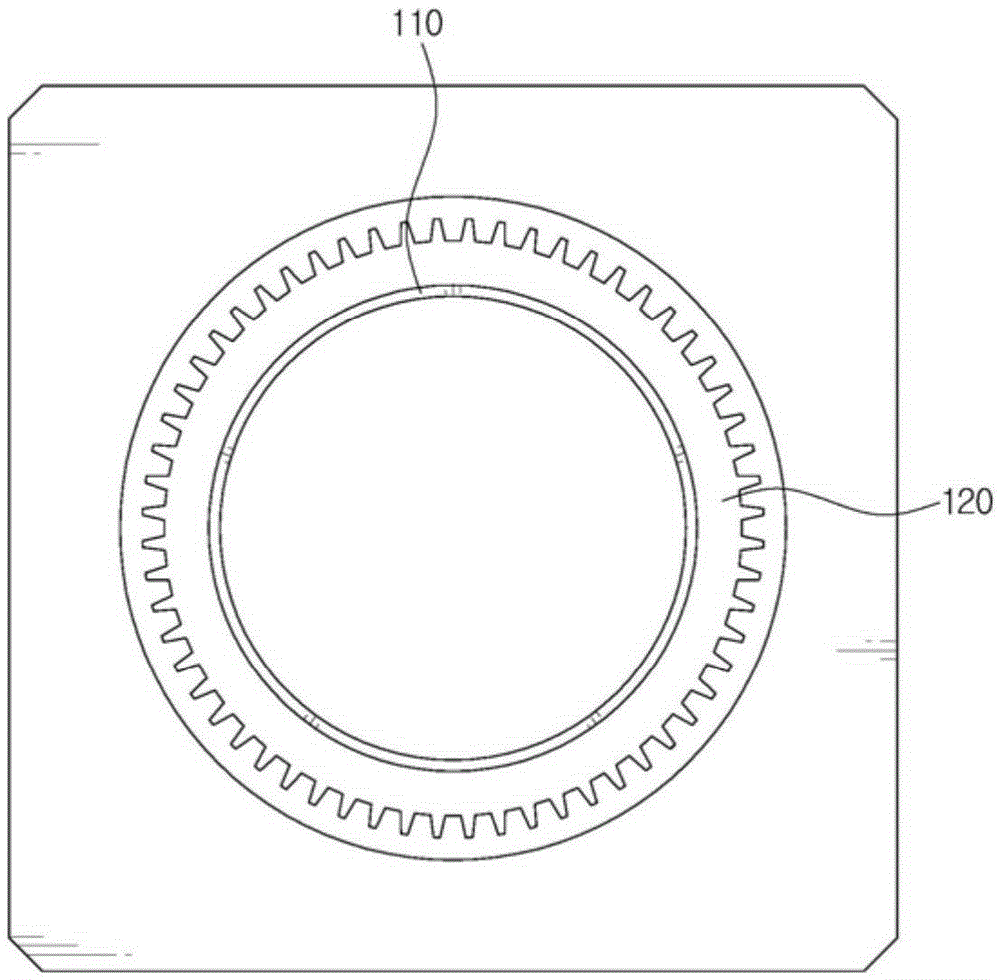
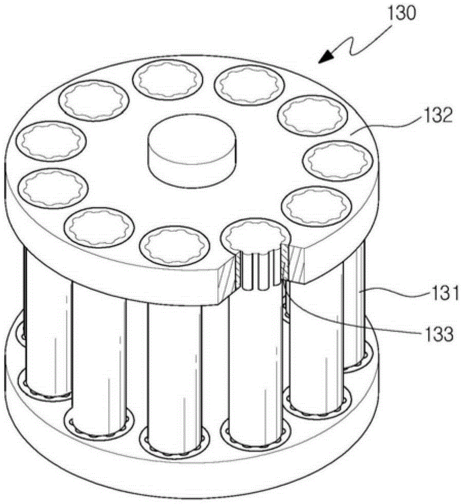
[0032] figure 1 It is a schematic perspective view of a substrate rotational alignment device according to an embodiment of the present invention. refer to figure 1 , the substrate rotation alignment device according to one embodiment of the present invention includes a connecting column 110, a rotary stage 120 for fixing the connecting column 110, and a power transmission part 130 that engages with the area of ​​the rotary s...


PUM


Abstract

The present invention relates to an apparatus for rotating and aligning a substrate, and more specifically to an apparatus for rotating and aligning a substrate which aligns a substrate on a mask in a deposition process. The present invention may include: a connection pillar connected to a settling part on which the substrate is settled; a rotating stage which is circular-shaped, fixed with the connection pillar, and a protruding part and a concave part are alternately formed; a power delivering unit which has multiple roller pins arranged separately from one another at fixed intervals, and delivers the power to the rotating stage by rotating in the state that at least one roller pin is pressured and adhered to the concave part at a region of the rotating stage; and a fixing unit which adheres at least one fixing pin to the concave part at another region in the rotating stage in order to have the opposite force of vector to the force applied to the rotating stage of the power delivering unit.

Description

technical field [0001] The present invention relates to a substrate rotation alignment device, and in more detail, relates to a device capable of preventing rotation of a rotary stage when a mounting part on which a substrate is mounted is rotated to align a substrate on a mask. Axis is twisted phenomenon of the substrate rotation alignment device. Background technique [0002] The revolution of information technology represented by digital fusion and ubiquitous has brought about the rapid development of electronic equipment. Among them, one of the technologies that constitute the core is display technology. Recently, demands for displays with further excellent visibility, low cost, and low power consumption have gradually increased. Subsequently, PDP (Plasma Display Panel, plasma display panel), liquid crystal display device (LCD: LiquidCrystalDisplay) and organic light-emitting diode (OLED: OrganicLightEmittingDiode) have attracted much attention. [0003] Organic light...

Claims


Application Information

Patent Timeline
IPC IPC(8): H01L21/68H01L51/56
CPCH01L21/682H10K71/164H10K71/166H01L21/68764H10K71/00
Inventor 李亨培安庆烈朴喜载
Owner SNU PRECISION CO LTD
Why Eureka
Try Eureka