Massaging device

A massager and metal plate technology, which is applied to kneading massage appliances, vibration massage, massage auxiliary products, etc., can solve the problems of increasing operating procedures and increasing the number of parts, and achieve the effect of preventing backlash or noise

Inactive Publication Date: 2006-09-06
SANYO ELECTRIC CO LTD
View PDF1 Cites 1 Cited by
  • Summary
  • Abstract
  • Description
  • Claims
  • Application Information

AI Technical Summary

Problems solved by technology

[0009] However, when the gearbox is separately installed on the chassis by fixing screws, etc., it is difficult to install the worm wheel and the worm with extremely small play due to installatio

Method used


Image

  • Massaging device
  • Massaging device
  • Massaging device

Examples


Embodiment Construction

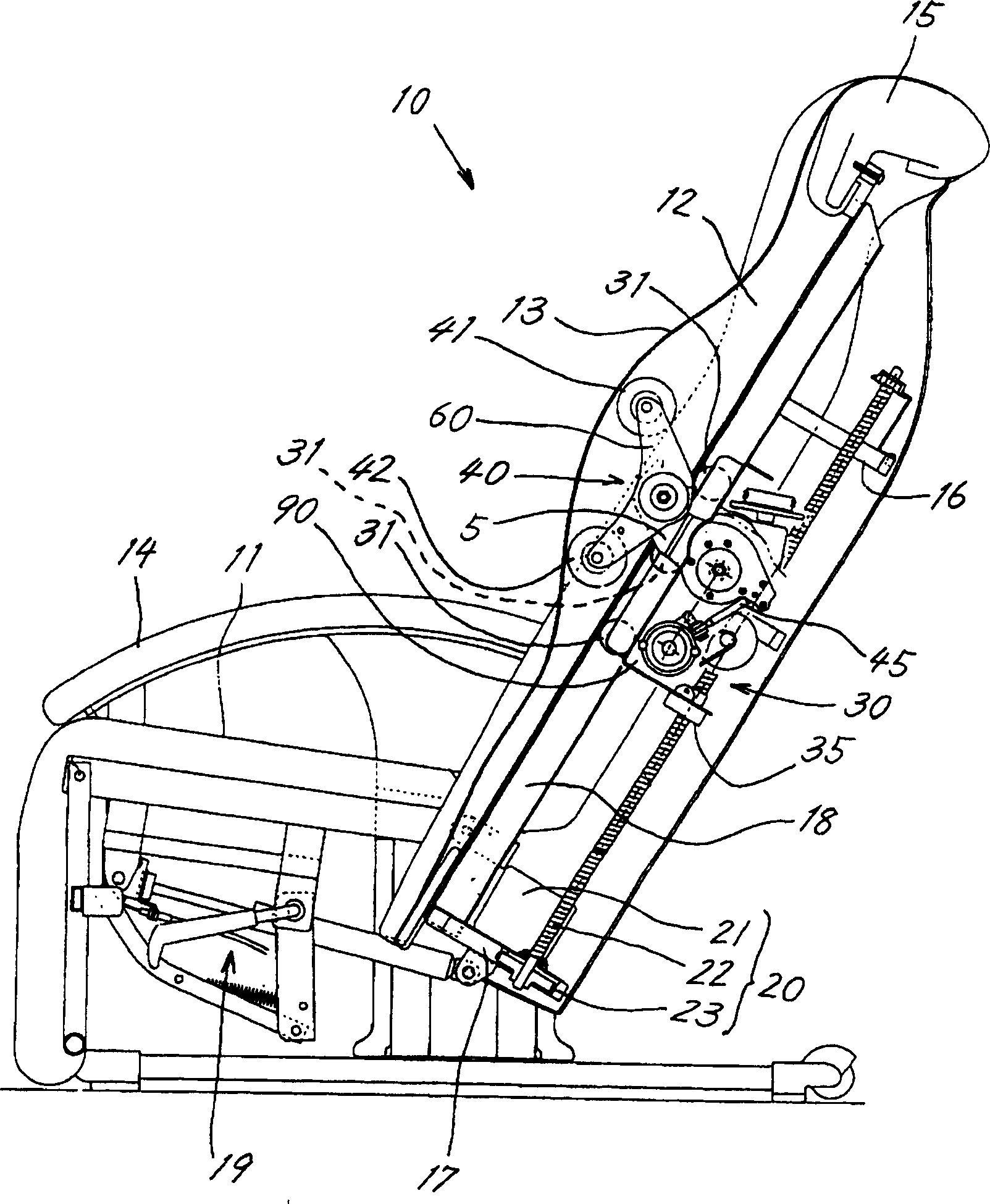
[0031] An example in which the present invention is applied to a chair type massager (10) will be described. In addition, this invention is not limited to a chair type, For example, it can be applied to a bed type massager, and can be applied also to a nursing bed etc.

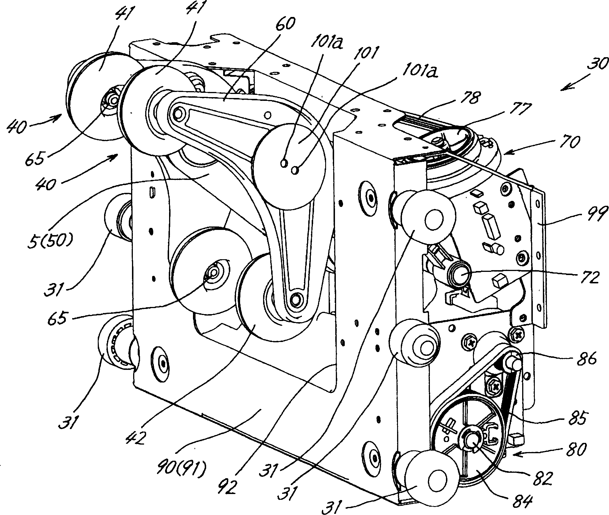
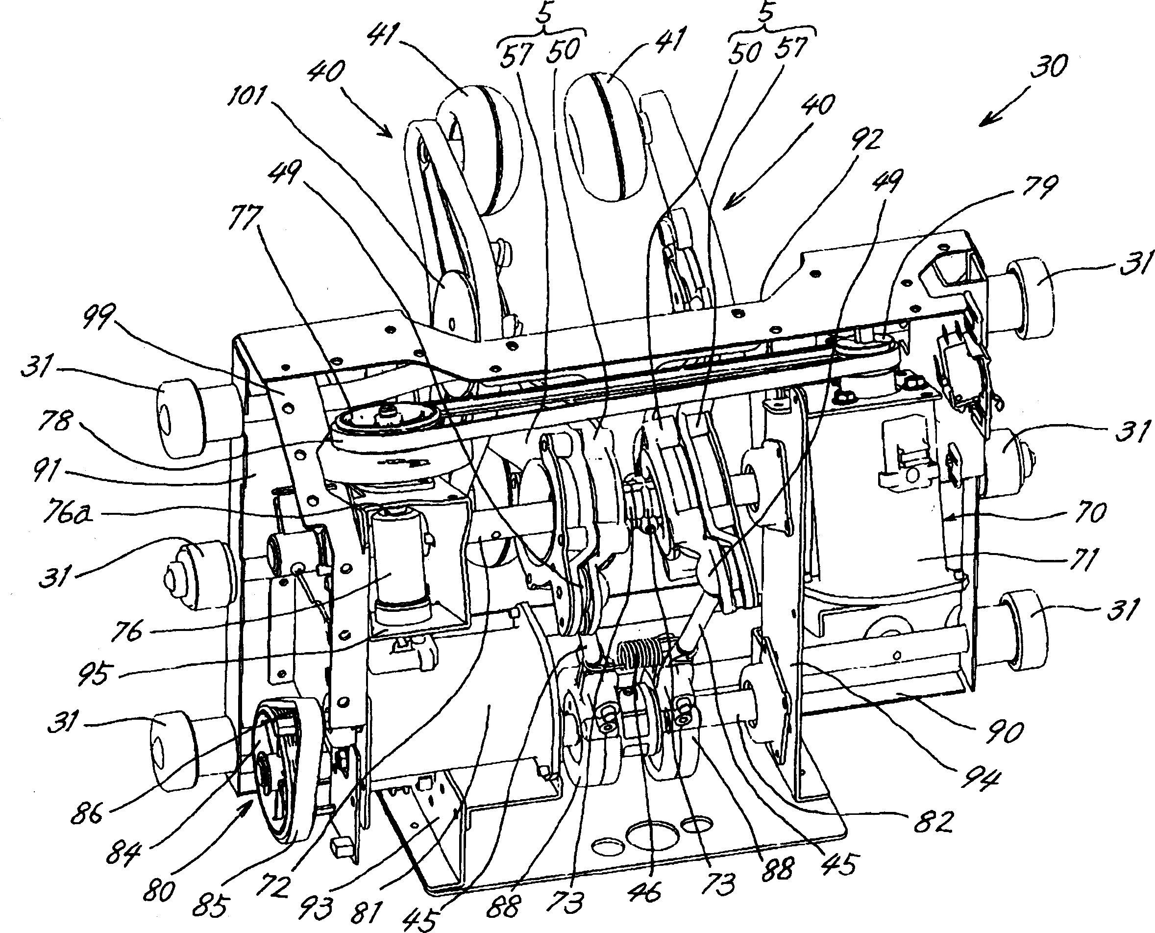
[0032] Furthermore, the feature of the present application is that the metal plate (93) of the chassis (90) is bent and the gear case (95) is directly formed on the metal plate (93), the massage unit (30) or the massage arm (5) The structure and action mechanism are not limited to the following embodiments.

[0033]

[0034] The seat of the massager (10), such as figure 1 As shown, it is composed of: the seat cushion part (11) where the person to be treated sits, the backrest part (12) formed upwardly from the rear end of the seat cushion part (11), and the seat cushion part (11) formed upwardly from the left and right sides. The armrest portion (14) constitutes. The seat cushion part (11), backrest part ...


PUM


Abstract

The invention provides a gear box forming a retarding mechanism by chassis, and a massage appliance with a certain axial distance between worm gear and worm. The massage appliance comprises: massage unit (30), which is formed by embarking the massage axis (72) equipped with treating finger (40), massage generator (71) driving said massage axis and reducing mechanism connected by way of transmitting force between massage axis and massage generator on metal chassis (90). The massage appliance is characterized in that the gear box (95) on reducing mechanism is formed by bending the metal board (93) on chassis.

Description

technical field [0001] The present invention relates to the improvement of the chassis of a massage unit equipped with therapeutic fingers, specifically, a massager in which the gear box of the reduction mechanism can be formed from the chassis. Background technique [0002] Conventionally, chair-type or bed-type massagers for massaging affected parts such as shoulders and waists of a person to be treated are known. As such a massager, for example, in Patent Document 1, a pair of left and right treatment fingers with massage balls are equipped up and down on the backrest against which the back of the treated person leans, and the treatment fingers are assembled in the massage unit installation. [0003] The above-mentioned massager makes the treatment finger reciprocate in the up-and-down direction and the horizontal direction including the front and back directions, and performs percussion massage or rubbing massage on the affected part through the massage ball, so that th...

Claims


Application Information

Patent Timeline
IPC IPC(8): A61H7/00A61H23/02
Inventor 古家义也常峰丰彦吉川知也铃木孝诚
Owner SANYO ELECTRIC CO LTD
Why Eureka
Try Eureka