Scroll device integrating a feed pump

a technology of a scroll device and a feed pump, which is applied in the direction of roller bearings, rotary piston engines, bearings, etc., can solve the problems of high temperature change sensitivity, deformation and displacement of scrolls, and significant limitations on the rotational speed which may be achieved, so as to prevent thermal deformation of scrolls, prevent thermal deformation, and increase flexibility

Inactive Publication Date: 2010-10-07
ENEFTECH INNOVATION
View PDF26 Cites 30 Cited by
  • Summary
  • Abstract
  • Description
  • Claims
  • Application Information

AI Technical Summary

Benefits of technology

[0021]According to another advantageous embodiment, means for preventing thermal deformations of the scrolls are provided. These means for preventing thermal deformations are preferably formed by an expansion ring introducing a local force which deforms the mobile scroll of the corresponding stage in the direction opposite to its normal deformation direction.
[0022]According to a third aspect, the present invention concerns a scroll device including two coupled stages on a rotary shaft, at both ends of an intermediate electric power device, wherein the first stage is formed by a first pressure variation device, wherein the first stage is formed by a first pressure variation device according to the first aspect, characterized in that the second stage is formed by a second pressure variation device with second admission and outlet ports decoupled from the admission and outlet ports of the first pressure variation device, respectively. Such a scroll device ensures operating independence of both stages and thereby provides a larger flexibility in terms of operating fluids, of connection between the stages and the electric power and between the stages themselves. Preferably the second pressure variation device is also a pressure variation device according to the first aspect.

Problems solved by technology

Originally, scroll devices were used for operating with fluids and refrigerants with relatively low pressure ratios corresponding to the limitation of an installed volume ratio.
Although they may handle a fluid with a high pressure ratio and are capable of integrating new functions such as expansion and compression simultaneously, such dual scroll devices suffer from a number of drawbacks among which the additional weight of the orbiting scrolls and the occurrence of a large inertial load on the bearings, the consequences of which are significant limitations on the rotational speed which may be attained.
Another recurrent problem with such scroll devices is the high sensitivity to temperature changes.
Compression or expansion of a fluid with a high temperature and pressure ratio is accompanied by a wide temperature distribution range resulting in deformations and displacements of scrolls.
The latter reveal various clearances in radial and axial directions where pressure losses, leakages and energy dissipation occur, reducing efficiency.
However, these heating structures are prohibitively expensive to manufacture.
This arrangement contributes to reducing the temperature difference between the scrolls but remains expensive to manufacture owing to the fact that the rear contact surfaces of both scrolls are made with a plurality of cooling fins which makes the scroll machining operation more difficult.
Additionally, as it is a source of heat losses during expansion, the use of cooling fins decreases the operating efficiency of the device.
With these ingenuities, it is by no means possible to reduce the energy losses of the fluid during its compression, nor is it possible to minimize the relative thermal deformations between the volutes (scrolls) in order to reduce their clearances.
Further, environmental issues related to check for oil and fluid (refrigerant) leaks in the atmosphere are increasingly important.
Nevertheless this design does not provide the sufficient characteristics and means for producing an expansion in series with a high pressure ratio nor for handling a fluid with a high temperature requiring a demand for additional cooling.
Nevertheless, this document presents a system with many limitations in terms of possible efficiency, temperature, pressure ratio and rotational speed.
Consequently, for example, during operation of two pairs of scrolls at a high temperature, cooling the generator will enhance the differential temperature between the front and rear contact surfaces of the orbiting scrolls, which will have the effect of increasing heat losses and pressure leaks due to deformations and therefore the result of substantially reducing the efficiency of the device.
Also, both pairs of scrolls are not suitable for expansion or compression with two serial stages, they should only be actuated in a parallel operating mode with a same operating fluid and with a limited pressure ratio owing to the fact that the low pressure peripheral ports of the orbiting scrolls directly communicate with the ports of the casing (housing) via the interior volume of the casing.
Further, the use of a gas throttle for maintaining a specific rotational speed contributes to destroying the pressure for a wide range of working conditions and is therefore not effective for modulating the cooling capacity.
Nevertheless, the use of scroll devices for applying a heat recovery system is not provided in such a system.
Further, this system does not provide any means for thermally insulating the volutes or any protection against thermal deformations.
Consequently, none of these applications is intended to provide a scroll device comprising an expander stage, a motor and using a pump for supplying the operating fluid.

Method used


Image

  • Scroll device integrating a feed pump
  • Scroll device integrating a feed pump
  • Scroll device integrating a feed pump

Examples


Embodiment Construction

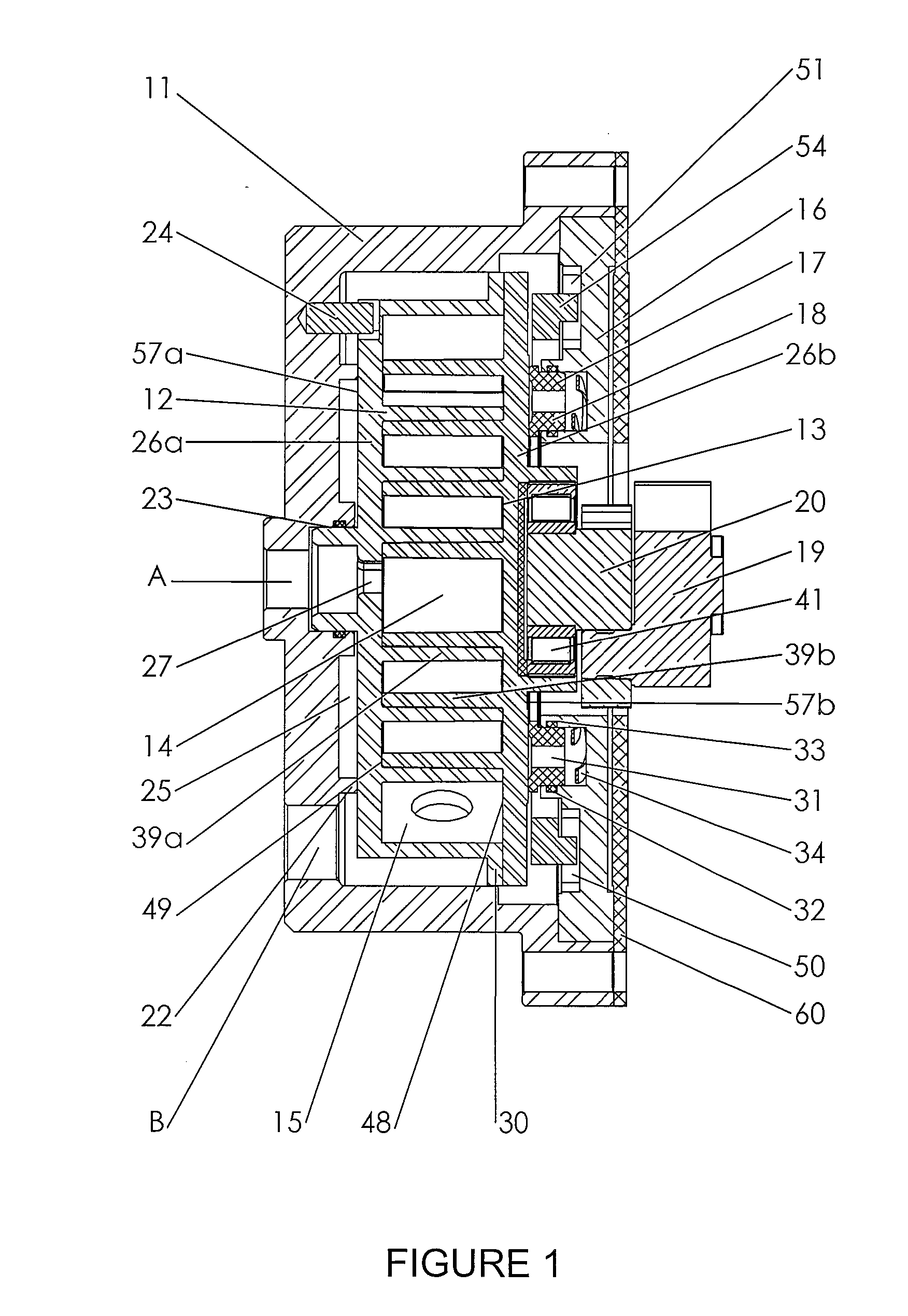
[0041]In the following description of the scroll device according to the present invention, for reasons of convenience, reference will primarily be made to a configuration with one or two expander stages, except for FIG. 10, wherein the second stage comprises a feed pump. However, it is clear that each stage of the scroll device which represents a scroll module may operate either as an expander or as a compressor. It will also be understood that it is possible to have a configuration with a single stage possibly coupled with an electric device, the module alone being able to be used as an expander or a compressor. For this purpose, it will be further noted that the second stage is preferably modular, i.e. interchangeable, so as to allow a modification of the operation of the device. However, alternatively, the second stage may be integral with the remainder of the device, i.e. non-modular.

[0042]The present description will now be provided as non-limiting examples in connection with ...


PUM


Abstract

A scroll device including two coupled stages on a rotary shaft, at both ends of an intermediate electric power device, wherein the first stage is formed by a first pressure variation device of an operating fluid, comprising a scroll case containing a fixed scroll and a mobile scroll relatively to the case, and with admission and outlet ports, and wherein the second stage is a feed pump which pumps the operating liquid and provides it in return.

Description

[0001]REFERENCE TO RELATED APPLICATIONS[0002]This application is a continuation of U.S. patent application Ser. No. 12 / 678,393, filed Mar. 16, 2010 which is hereby incorporated by reference and which is the nationalization of PCT / EP2008 / 063668, filed 10 Oct. 2008 which is hereby incorporated by reference. This application claims priority from Patent Application No. CH 1612 / 07, filed 17 Oct. 2007 which is hereby incorporated by reference.TECHNICAL FIELD[0003]The present invention generally relates to a scroll device integrating a feed pump. According to another aspect, the present invention relates to a pressure variation device formed with a simple scroll device, of a compressor or expander type, or a scroll device including two coupled stages on a rotary shaft and positioned at both ends of an intermediate electric power device (motor or generator). According to another aspect, the present invention more particularly relates to a simple scroll or two-stage scroll device with which ...

Claims


Application Information

Patent Timeline
Patent Type & Authority Applications(United States)
IPC IPC(8): F04B35/04F01C1/02
CPCF04C18/0215F04C28/06F16C35/077F16C19/26F16C19/52F04C29/04F16C2360/42
Inventor KANE, MALICKCRETEGNY, DANILOMERMINOD, ANTOINE
Owner ENEFTECH INNOVATION
Why Eureka
Try Eureka