Exhaust control valve

a technology of exhaust control valve and control valve body, which is applied in the direction of valve operating means/release devices, combustion air/fuel air treatment, machines/engines, etc., can solve the problems of difficult to maintain high sealing properties, thermal deformation due to partial material thickness, and the body of crank-like valve suffers from some disadvantages

Inactive Publication Date: 2003-12-02
HONDA MOTOR CO LTD
View PDF15 Cites 28 Cited by
  • Summary
  • Abstract
  • Description
  • Claims
  • Application Information

AI Technical Summary

Benefits of technology

Since the valve body and the valve shaft have a coaxial cylindrical shape, it is possible to obtain good distribution of melt from a central portion of an end of the valve shaft at the time of casting, and to prevent thermal deformation from occurring due to partial material thickness. Accordingly, the external peripheral surfaces of the valve body and the valve shaft can be finished by cutting continuously after casting. Therefore, the valve body can be manufactured with high precision efficiently.
The high-precision valve body can have its external peripheral surface in thorough contact with the internal surface of the valve housing, so that it is possible to effectively restrain leakage of exhaust gas at the contact area and to carry out appropriate exhaust control. Further, since the cylindrical valve body has good weight balance about the axis line, it is possible to achieve a reduction of driving torque for the valve body and, hence, enhancement of response to the driving torque. Also, it is possible to minimize non-uniform loading on the bearing bushes, thereby contriving improved durability of the bearing bushes.

Problems solved by technology

However, this crank-like valve body suffers from some disadvantages.
Since the shape of the valve body is asymmetrical with respect to the axis line of the valve shaft, distribution of melt is often defective at the time of casting from an end of the valve shaft, and thermal deformation due to partial material thickness can easily occur.
In addition, since the crank portion serving as a valve portion makes contact with the valve housing over a small area, it is difficult to maintain high sealing properties.
Further, since the weight balance about the axis line of the valve body is offset / poor, response to driving torque is relatively poor.

Method used


Image

  • Exhaust control valve
  • Exhaust control valve
  • Exhaust control valve

Examples


Embodiment Construction

The present invention will now be described with reference to the embodiments illustrated by the accompanying drawings.

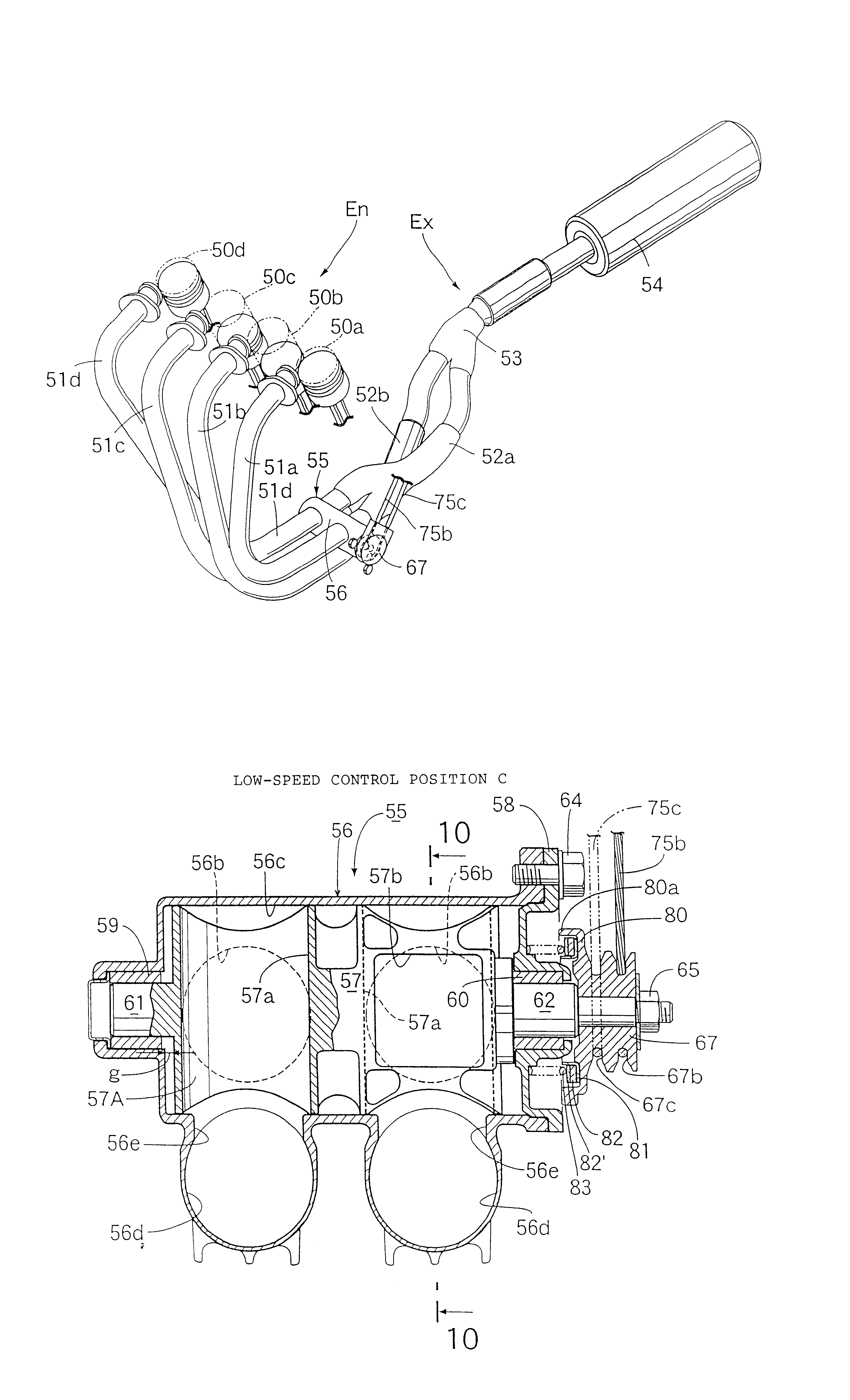
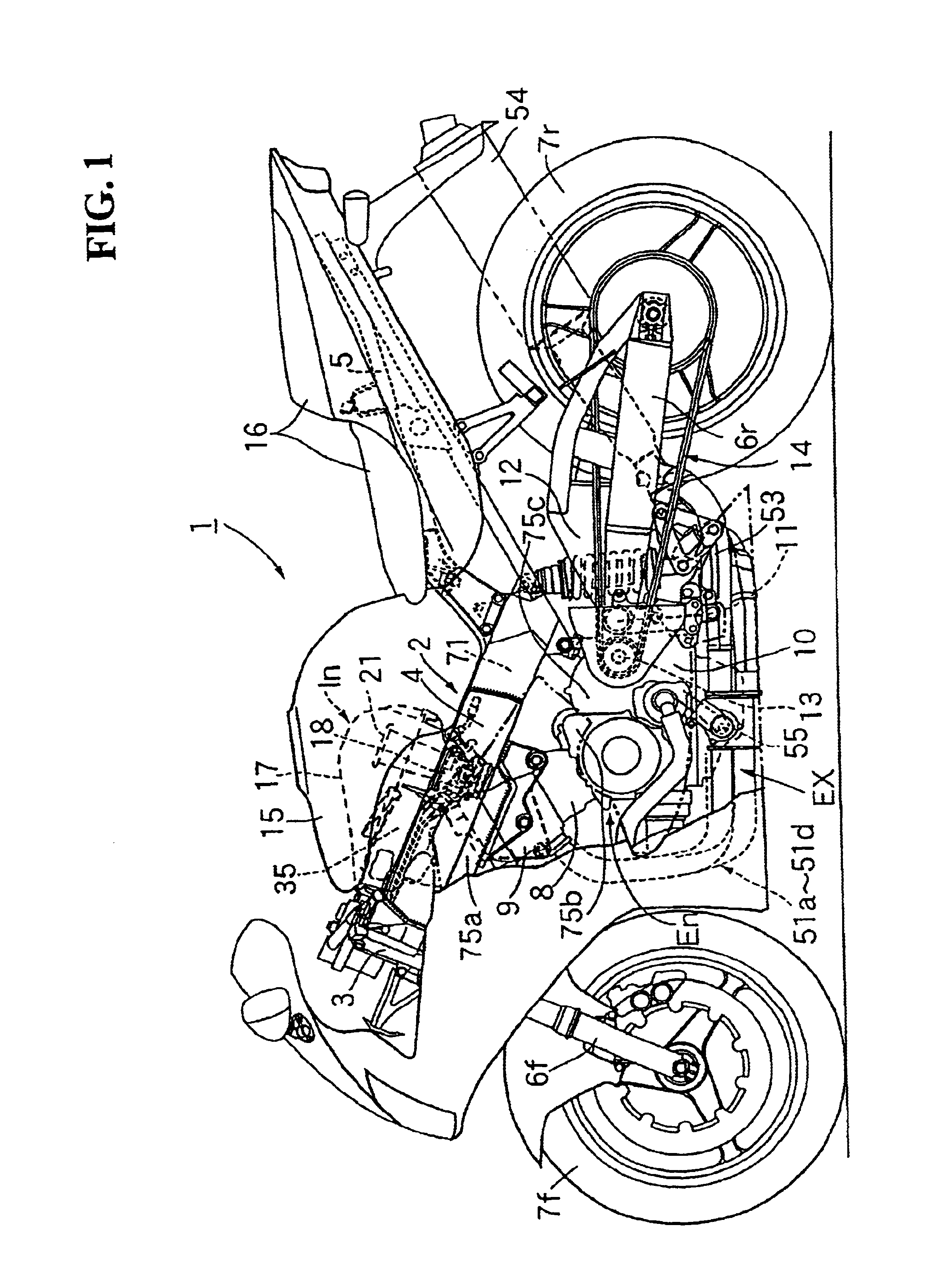
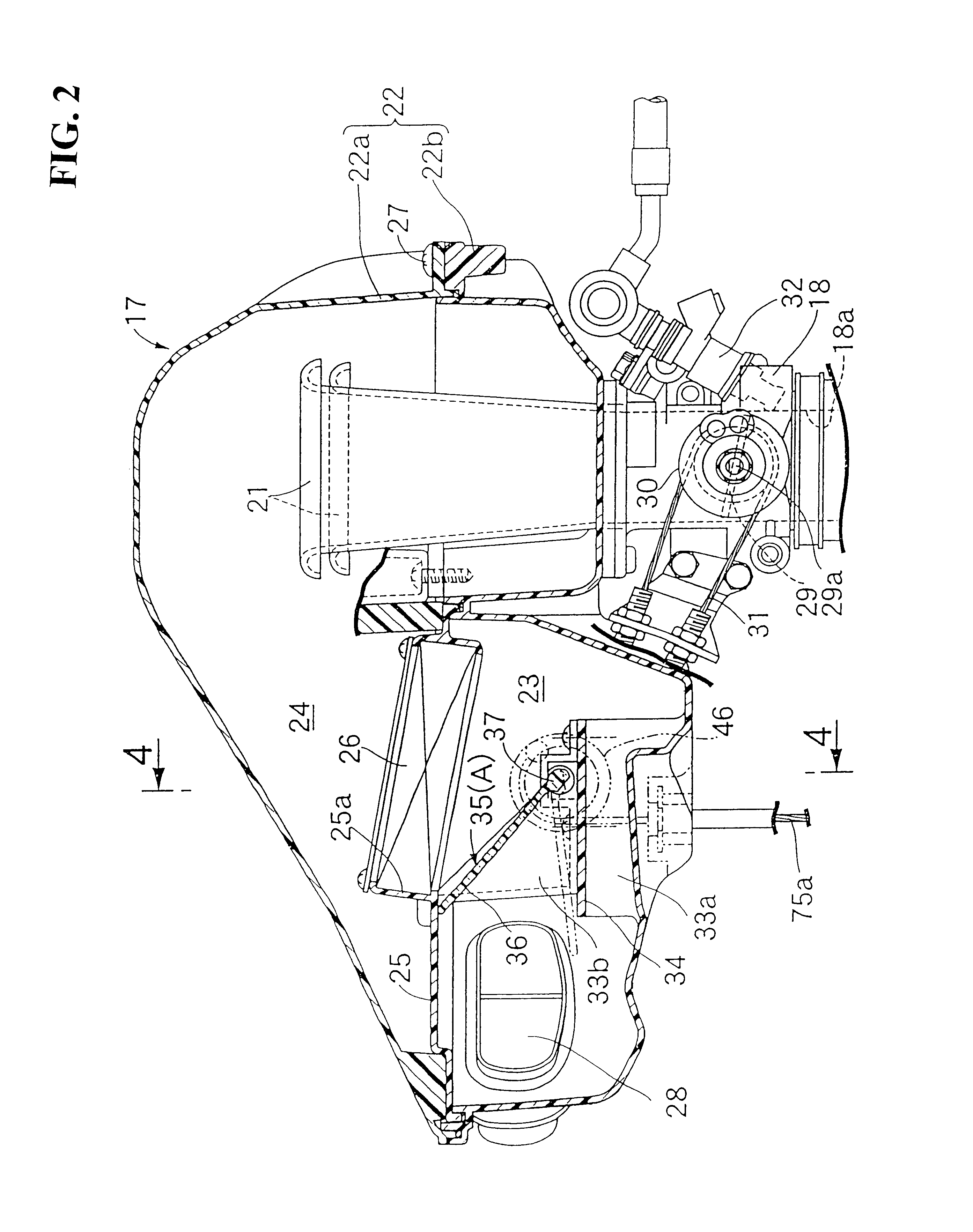
FIG. 1 is a side view of a motorcycle with an engine having an intake control device and an exhaust control device. FIG. 2 is a vertical sectional side view of a portion of an intake control device according to an embodiment of the present invention. FIG. 3 is a vertical sectional side view of a portion of an intake control device according to an embodiment of the present invention and corresponding to a different operational position than that of FIG. 2. FIG. 4 is a sectional view taken along line 4--4 of FIG. 2 according to an embodiment of the present invention. FIG. 5 is a sectional view taken along line 5--5 of FIG. 4 according to an embodiment of the present invention. FIG. 6 is a sectional view taken along line 6--6 of FIG. 4 according to an embodiment of the present invention. FIG. 7 is a perspective view of an exhaust system according to an embodiment of th...


PUM


Abstract

An exhaust control valve has a valve housing and a valve body rotatably contained within the valve housing. The valve body cooperates with the valve housing for controlling the flow of exhaust gas. A transmission member rotationally drives a valve shaft of the valve body. The valve body is formed in a cylindrical shape and coaxially with an axis line of the valve shaft. The valve body and the valve shaft are made from a one-piece body by casting. This arrangement provides an exhaust control valve for an engine having a valve body that provides excellent sealing properties, demonstrates high response to driving torque and is easy to manufacture through casting.

Description

1. Field of the InventionThe present invention relates to an exhaust control valve for controlling the flow of exhaust gas, and more particularly to an exhaust control valve for a motor vehicle exhaust gas system.2. Background ArtIn an exhaust control valve according to the background art as shown in Japanese Pre-examination Patent Publication (KOKAI) No. 63-212728 (1988), a cast valve having a crank-like shape has the flow of exhaust gas controlled by a crank portion.However, this crank-like valve body suffers from some disadvantages. Since the shape of the valve body is asymmetrical with respect to the axis line of the valve shaft, distribution of melt is often defective at the time of casting from an end of the valve shaft, and thermal deformation due to partial material thickness can easily occur. In addition, since the crank portion serving as a valve portion makes contact with the valve housing over a small area, it is difficult to maintain high sealing properties. Further, si...

Claims


Application Information

Patent Timeline
Patent Type & Authority Patents(United States)
IPC IPC(8): F01N3/28F01N7/14F02D9/04F02D9/00F02B61/02F02B61/00F02M35/00F02M35/16F16K5/06F16K31/44F16K31/46F02M35/10F02B75/00F02B75/18F02B27/06F01N13/08F01N13/14F02D9/16
CPCF01N3/28F16K31/465F01N13/14F02B61/02F02D9/04F02M35/10013F02M35/10039F02M35/10065F02M35/10216F02M35/10255F02M35/112F02M35/162F16K5/0647F01N3/2853F02B2075/1816
Inventor NAKAYASU, TETSUYASAGARA, MIKIOTAKAHASHI, KYOIWASE, NORITOSHIYAMADA, HAJIMEMURAKAMI, ATSUSHI
Owner HONDA MOTOR CO LTD
Why Eureka
Try Eureka