

Toroidal ion trap mass analyzer with cylindrical electrodes
- Summary
- Abstract
- Description
- Claims
- Application Information
AI Technical Summary
Benefits of technology
Problems solved by technology
Method used
Image

Examples
Embodiment Construction
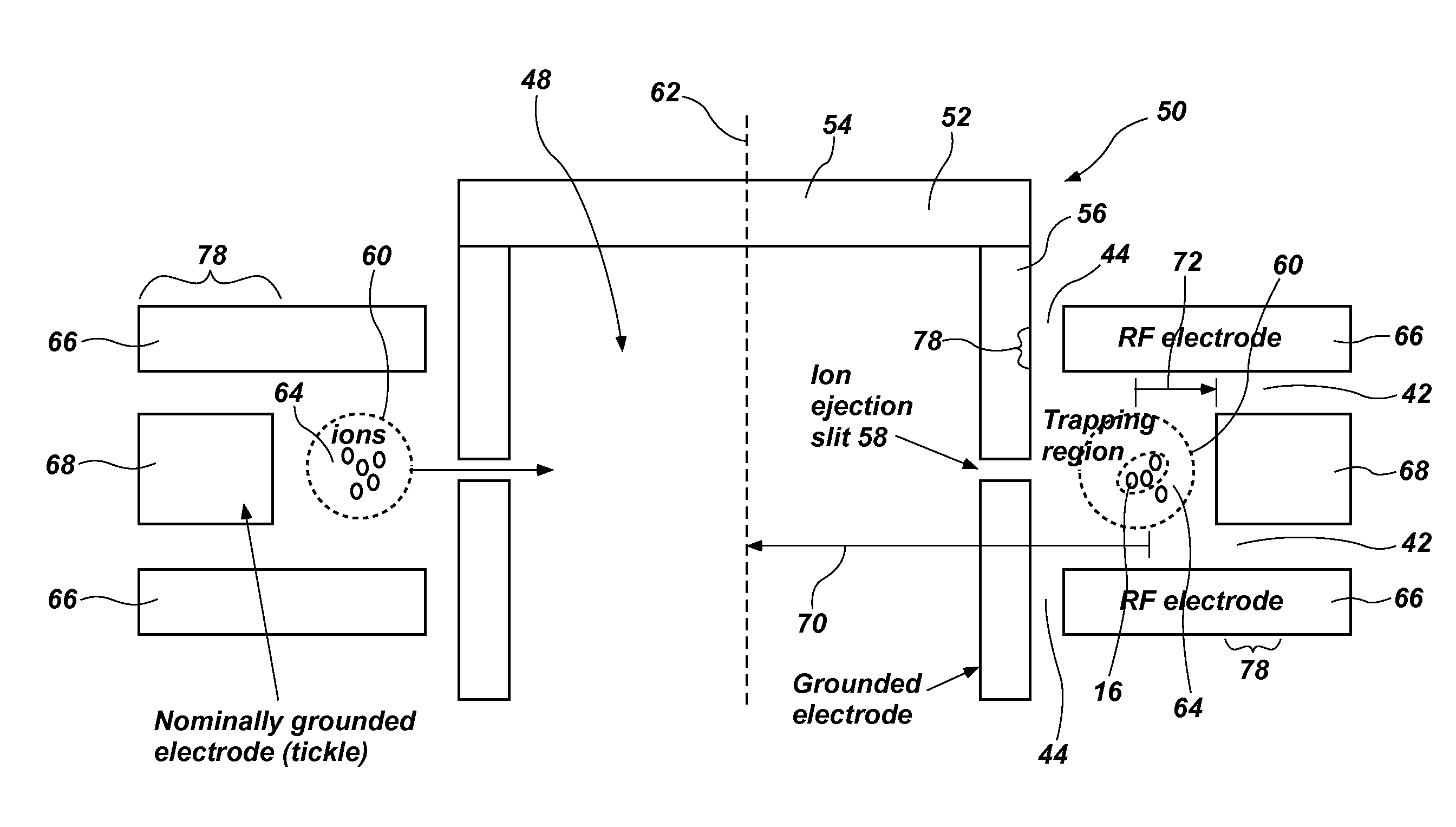
[0040]Reference will now be made to the drawings in which the various elements of the present invention will be given numerical designations and in which the invention will be discussed so as to enable one skilled in the art to make and use the invention. It is to be understood that the following description is only exemplary of the principles of the present invention, and should not be viewed as narrowing the claims which follow.
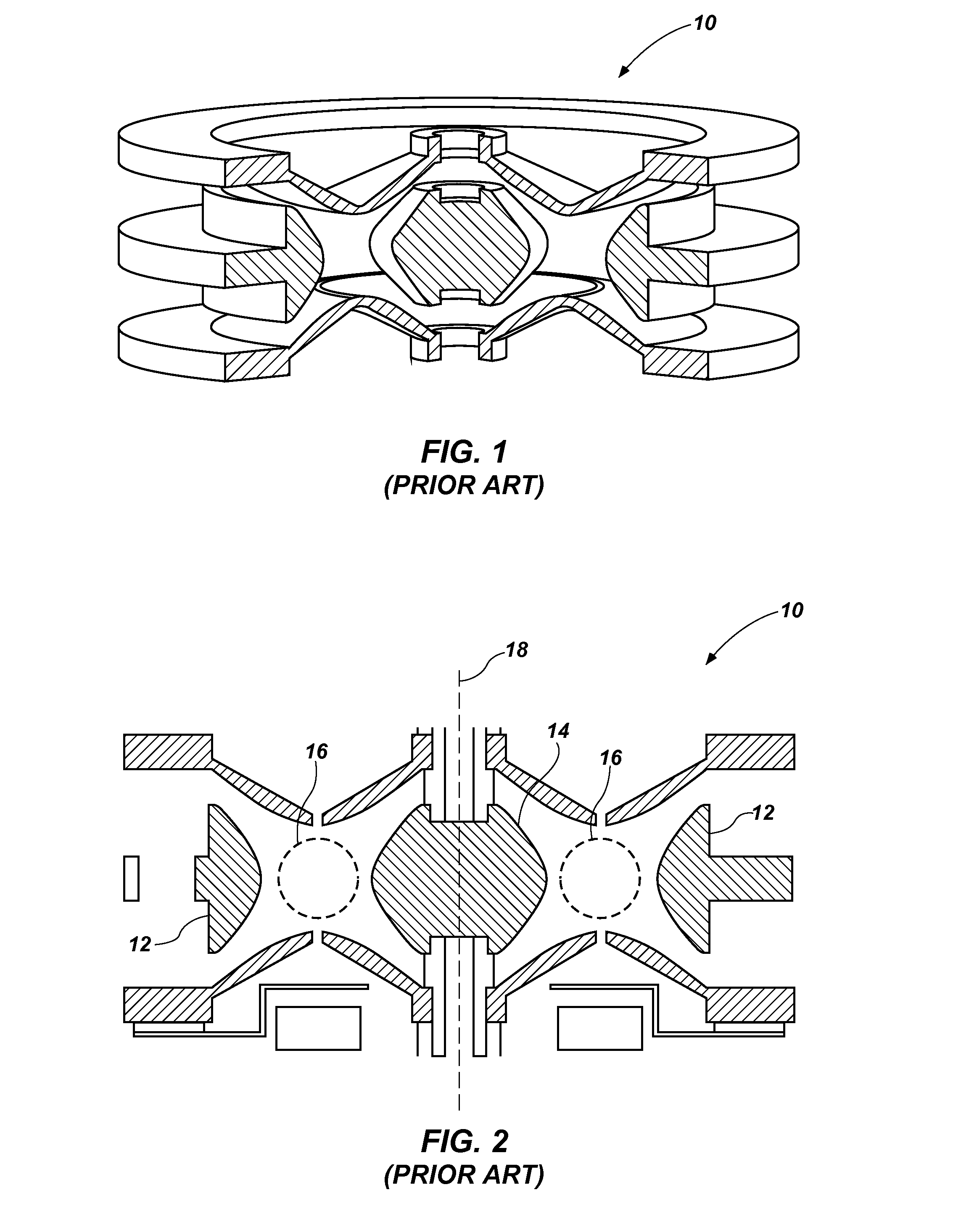
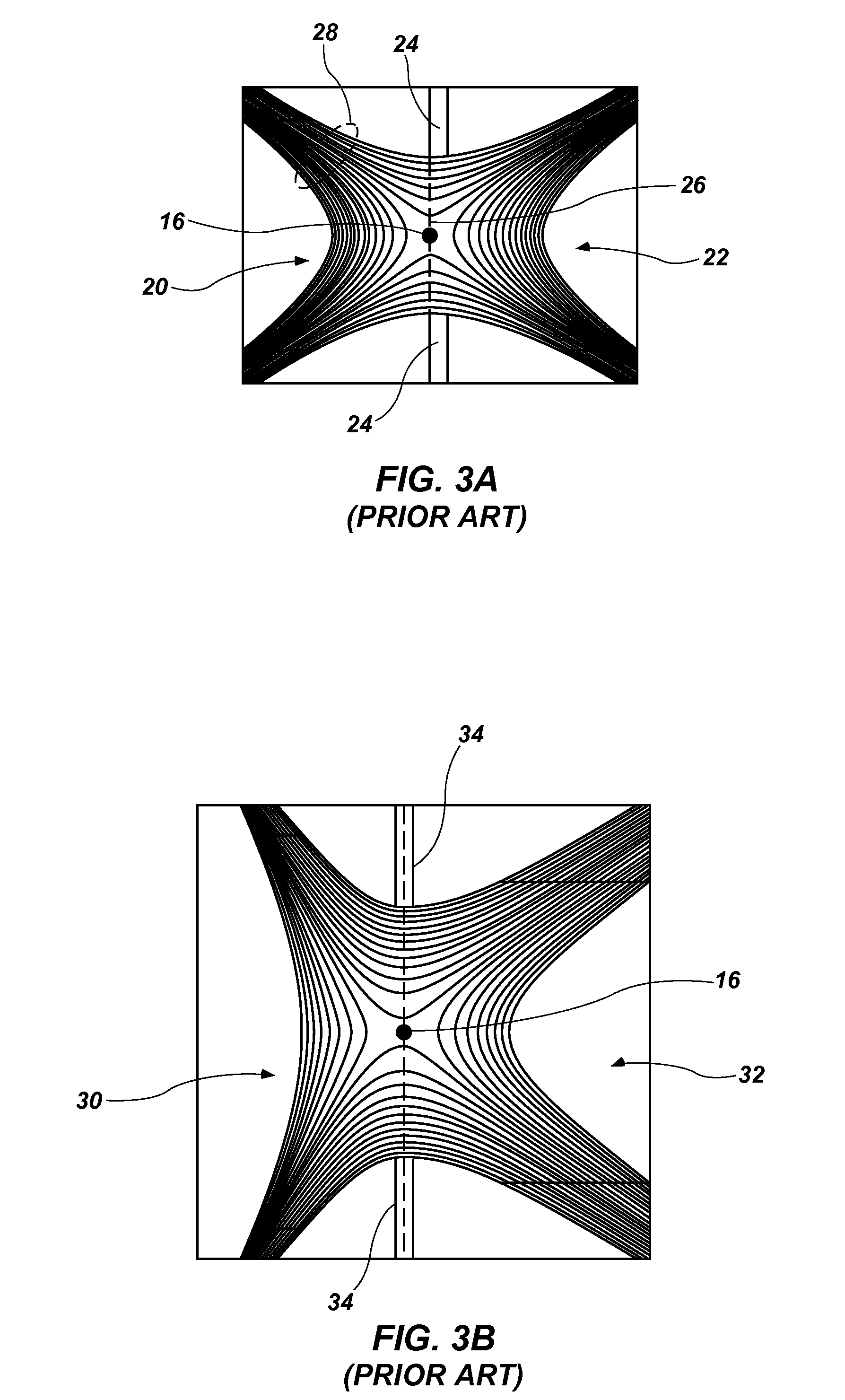
[0041]A mass analyzer ion trap that offers increased ion storage over other designs and is amenable to miniaturization is the toroidal RF ion trap mass analyzer, or hereinafter the toroidal ion trap. The toroidal ion trap can be viewed as either a conventional 3D ion trap cross section that has been rotated on an edge through space as shown in FIGS. 1 and 2, or as a linear quadrupole curved and connected end to end. In either case, distortions to the quadrupole trapping field introduced by the curvature of the storage region degrade the performance of the d...
PUM
 Abstract
Description
Claims
Application Information