Multiple piece reflective angle transformer

A technology of reflection ring and reflector, applied in the direction of reflector, semiconductor devices of light-emitting elements, electrical components, etc.

Active Publication Date: 2008-10-29
SIGNIFY NORTH AMERICA CORP
View PDF1 Cites 5 Cited by
  • Summary
  • Abstract
  • Description
  • Claims
  • Application Information

AI Technical Summary

Problems solved by technology

[0003] However, when the light output of an LED lighting system is narrowly specified for a system including, for example, agreement-limited systems, such as for projection displays (e.g., rear-projection

Method used


Image

  • Multiple piece reflective angle transformer
  • Multiple piece reflective angle transformer
  • Multiple piece reflective angle transformer

Examples


Embodiment Construction

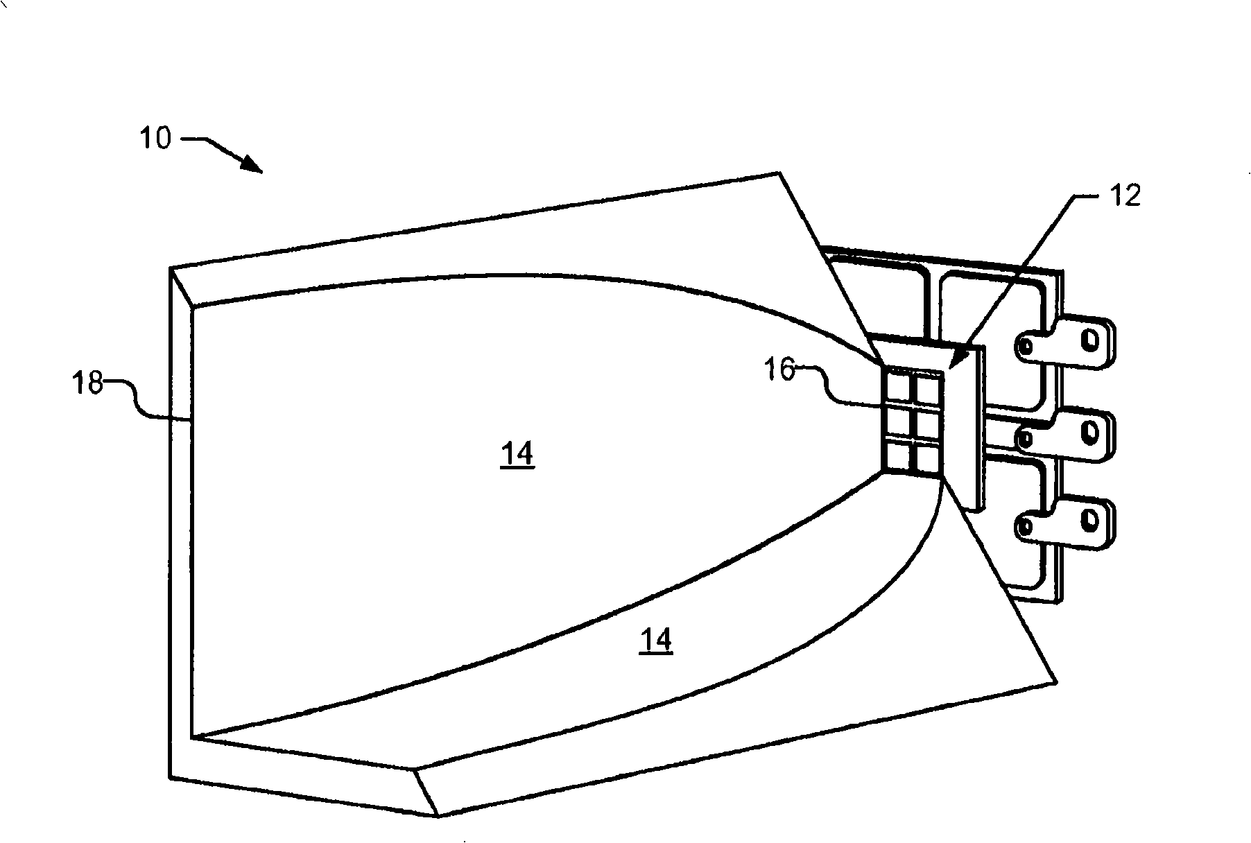
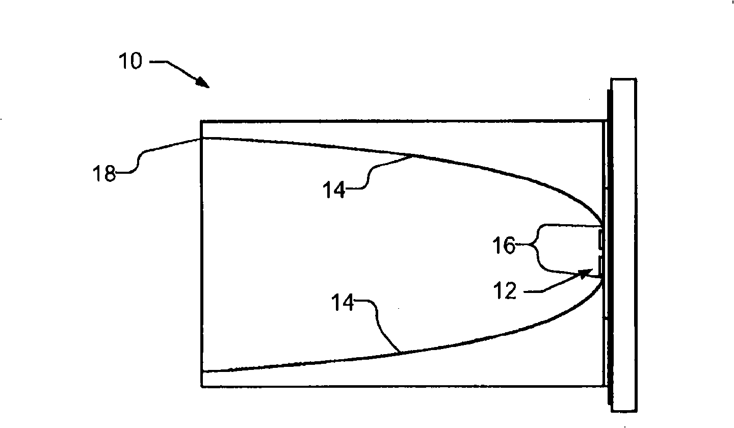
[0010] figure 1 with figure 2 A cross-sectional perspective view and a cross-sectional view of the light concentrating device 10 used with the light emitting diode array 12 are shown. The light concentrating device 10 may be, for example, a reflection angle converter, which is used to collimate the light emitted from the array 12. As can be seen, the light concentrating device 10 includes a continuous reflective side wall 14. Therefore, from the edge 16 of the reflective sidewall closest to the array 12 to the end 18 of the reflective sidewall, the concentrating device 10 is one piece.

[0011] In order to improve efficiency, it is desirable that the edge 16 of the reflective sidewall 14 is as close to the array 12 as possible. Moreover, in order to reflect any light emitted through the sidewall of the LED, the edge 16 should be a knife edge. Therefore, the light concentrating device 10 requires high-precision manufacturing and high-precision arrangement of the light concentrat...


PUM


Abstract

Collection optics (10) are used with one or more light emitting diodes (106) to produce, e.g., collimated light. The collection optics (10) are produced in multiple pieces including a small reflective ring (102) that surrounds the one or more light emitting diodes (106). The reflective ring (102) may be positioned relative to the LEDs (106), using a mesa (112) upon which the LEDs (106) are mounted, as a lateral positioning guide. A separate upper reflector (104) uses the reflective ring (102) as a lateral positioning guide during assembly. The reflective ring (102) and the upper reflector (104) include reflective sidewalls that are approximately continuous when the reflective ring (102) and upper reflector (104) are assembled.

Description

Invention field [0001] The present invention relates to light emitting diodes (LEDs) or other solid-state light sources, and in particular to collection optics for these light sources. Background technique [0002] The light emitting diode die usually emits light at a wide angle, for example, as wide as 90 degrees off the central axis. It is common to use a lens or a reflective cup to change the direction of the light emitted by the LED. For equipment used as indicator lights or occasions that do not require precise emission patterns, this simple optical technique is sufficient. [0003] However, when the light output of the LED lighting system is narrowly designated for use in one system including, for example, a system with limited protocols, such as for projection displays (e.g., rear-projection TV or front-projection projector), automotive applications (e.g., , Headlights), fiber optics, accent lighting, color mixing in compact spaces and other applications, innovative optica...

Claims


Application Information

Patent Timeline
IPC IPC(8): F21K7/00F21V7/00F21K99/00H01L33/60
CPCY10S362/80F21V17/005F21K9/00F21V7/0025F21Y2101/02H01L33/60F21Y2115/10F21K9/68
Inventor G·W·恩格M·法尔M·H·库帕S·埃伯尔F·J·小瓦尔
Owner SIGNIFY NORTH AMERICA CORP
Why Eureka
Try Eureka