Milling Machine and Blank for a Dental Component

a technology of dental components and milling machines, which is applied in the fields of dentistry, medical science, chucks, etc., can solve the problems of incomplete connection geometry, workpieces fabricated from blanks, and inability to meet the connection geometry

Active Publication Date: 2017-11-09
AMANN GIRRBACH
View PDF13 Cites 4 Cited by
  • Summary
  • Abstract
  • Description
  • Claims
  • Application Information

AI Technical Summary

Problems solved by technology

No connection geometry is yet provided according to present prior art during the fabrication of the dental component, in particular the crown or an abutment.
Furthermore, clamping the blanks into the milling machine is not provided unambiguously with respect to the alignment of the workpiece later to be obtained, and slight miss-positioning of the blank, such as, for example, canting, can occur during clamping into the milling machine, so that the workpiece fabricated from the blank can comprise faults.
The problem there arises that even minor faults during clamping and misalignment between the devices for securing a desired orientation and the holder can have a considerable influence on the quality of the dental component.

Method used


Image

  • Milling Machine and Blank for a Dental Component
  • Milling Machine and Blank for a Dental Component
  • Milling Machine and Blank for a Dental Component

Examples


Embodiment Construction

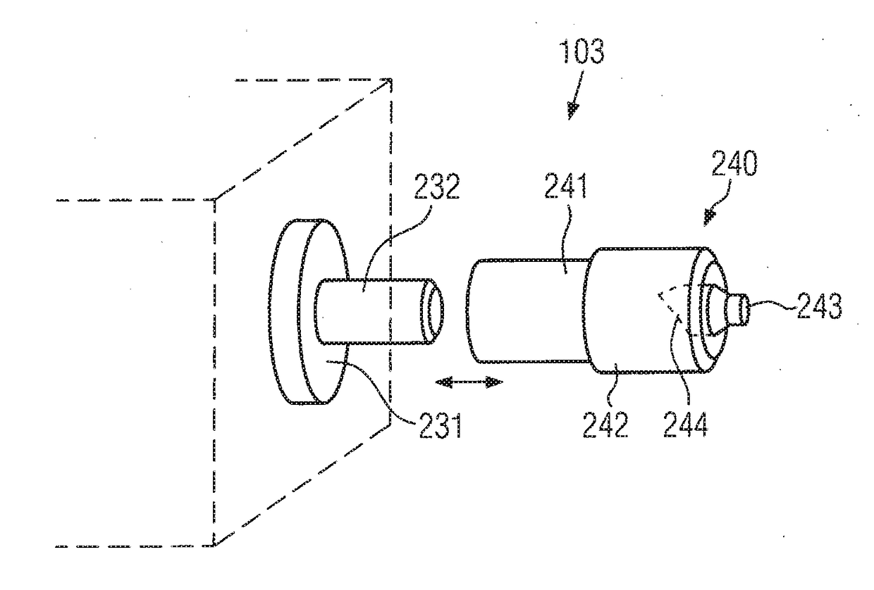
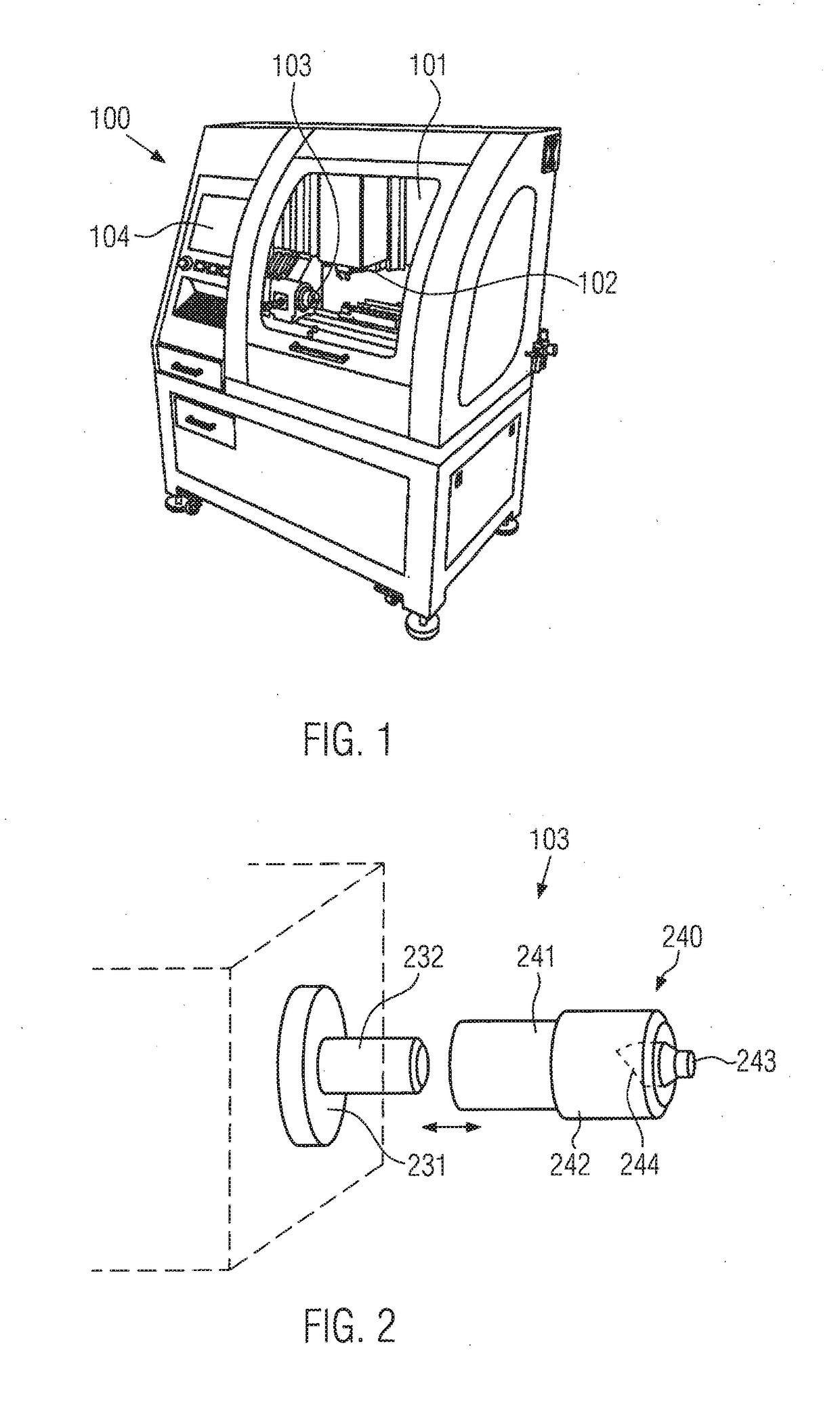
[0046]FIG. 1 schematically shows the basic structure of a milling machine 100, as it is also known, for example, from prior art. This milling machine can comprise a cover 101 in which the remaining components of the milling machine are arranged. The cover can be divided into several individual regions and in particular comprise an inspection region through which the component can be observed during production. Furthermore, a hatch or the like can be provided in order to introduce a blank from which a toothed technical component, such as a crown, is to be produced, into milling machine 100. In addition, but not necessarily, an operating terminal 104 can be provided on milling machine 101, which, for example, allows data input with regard to the manufacture of the dental component. Milling machine 100 further comprises one or more cutting tools 102 with which a blank inserted into milling machine 100 can be machined. Furthermore, a holding device 103 is provided in a holding region in...


PUM

PropertyMeasurementUnit
distanceaaaaaaaaaa
distanceaaaaaaaaaa
distanceaaaaaaaaaa

Abstract

The invention relates to a milling machine for producing a dental component, such as a crown or an abutment for example, from a blank. The milling machine includes a stop and a holder for the blank. The invention is characterized in that the holder is designed such that the holder can be surrounded by a mounting, which surrounds the holder, of the blank, and the surrounding mounting of the blank can be brought into contact with the stop for positioning purposes. The invention further relates to a corresponding blank.

Description

[0001]The invention relates to a milling machine for producing a dental component from a blank according to the preamble of claim 1 and a blank from which a dental component can be milled according to the preamble of claim 8.PRIOR ART[0002]For the production of dental components, such as, for example, crowns or abutments, inter alia milling machines are used. Milling machines in connection with dental technology are therefore known from prior art.[0003]For example, US 2006 / 0035776 A1 shows a milling machine, where a blank is via a spindle having a specific shape inserted into a respective mounting of the milling machine. Any connection geometry is there not yet defined by the blank or a part which is respectively connected to the blank, so that this is only defined later in the course of the production process.[0004]Furthermore, US 2012 / 0214133 A1 discloses securing the blank, from which the later dental component is to be formed, via a screw connection which is connected to the bla...

Claims


Application Information

Patent Timeline
Patent Type & Authority Applications(United States)
IPC IPC(8): A61C13/00A61C5/77
CPCA61C13/0022A61C13/0006A61C5/77B23B31/1075A61C13/0004Y10T279/17821Y10T409/305824Y10T409/308736Y10T409/308792
Inventor SCHELLING, PETERANDERS, JOHANNES
Owner AMANN GIRRBACH
Why Eureka
Try Eureka