
Method for manufacturing surface unevenness

A technology of surface unevenness and production method, which is applied in the direction of photoengraving process, application and instrument of pattern surface, and can solve problems such as difficulty in forming unevenness.

Inactive Publication Date: 2010-01-27
KIMOTO CO LTD
View PDF4 Cites 5 Cited by
  • Summary
  • Abstract
  • Description
  • Claims
  • Application Information

AI Technical Summary

Problems solved by technology

However, depending on conditions such as the material of the material and the pressure at the time of pressing, the surface unevenness formed on the same mold may not necessarily be the same, and it is difficult to form unevenness on all materials with good reproducibility.

Method used


Image

  • Method for manufacturing surface unevenness
  • Method for manufacturing surface unevenness
  • Method for manufacturing surface unevenness

Examples


Embodiment 1

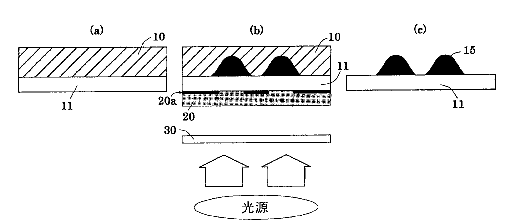
[0088] A resist (EKIRESIN PER-800RB-2203: Koyo Chemical Industry Co., Ltd.) was coated on a substrate 11 made of a polyester film (Coslnoshine A4300: Toyobo Co., Ltd., refractive index 1.64) with a thickness of 100 μm and dried to form a thickness 100 μm photosensitive film 10 .

[0089] Next, a film (Light-Up TL2: KIMOTO Co., Ltd.) having a light-diffusing member with an external haze of 30% was prepared.

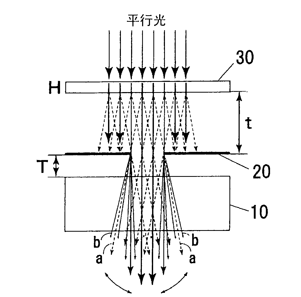
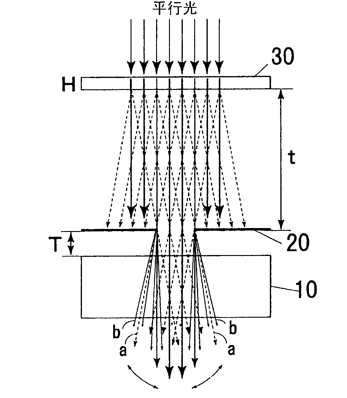
[0090] Then, the substrate 11 of the photosensitive film 10 is superimposed on the light-shielding surface 20a of the chromium mask 20 (hereinafter referred to as the Cr mask) having a plurality of circular openings formed thereon, and then the distance from the light-shielding surface of the Cr mask is 8.3 After setting the film with the light diffusing member 30 at mm ( Figure 10), the photosensitive film was exposed from the Cr mask side under the following conditions. Among them, two types of Cr masks having a mask diameter of 30 μm and 40 μm were prepared, and expo...

Embodiment 2~5

[0094] Except that the polyester film thickness of the substrate 11 to be the photosensitive film 10 and the external haze of the light-diffusing member 30 were changed as shown in Table 1, in the same manner as in Example 1, a film having unevenness formed on the surface of the substrate was obtained. sample. Among them, as a film having a light-diffusing member with an external haze of 65%, Light-Up SP6 (product name) from KIMOTO Co., Ltd. was used, and as a film having a light-diffusing member with an external haze of 86% , Light-Up DP8 (product name) of KIMOTO Co., Ltd. was used.

Embodiment 6

[0096] Except having used the film of the following Example 6 as a film which has a light-diffusion member, it carried out similarly to Example 1, and obtained the sample which formed the uneven|corrugated on the base material surface.

[0097] On a base material comprising a polyester film (Cosmoshine A4300: Toyobo Co., Ltd.) with a thickness of 50 μm, a light-diffusing member coating solution of the following formulation is applied and dried so that the thickness after drying is 5 μm, and then the light-diffusing The same polyester film was laminated on the member to form a light-diffusing member 30 having an internal haze of 5%, and a film having a light-diffusing member (film of Example 6) was obtained.

[0098]

[0099] ·Acrylic resin 100 parts

[0100] (ACRYDIC A-807: Dainippon Ink Chemical Industry Co., Ltd.)

[0101] (solid content 50%)

[0102] ·Spherical particles (silicon dioxide) 3 parts

[0103] (TOSPEARL 105: GE Toshiba Silicone Corporation)

[0104] (refra...


PUM

PropertyMeasurementUnit
refractive indexaaaaaaaaaa
roughnessaaaaaaaaaa
turbidityaaaaaaaaaa

Abstract

The inventon provides a method for manufacturing surface unevenness, by which a desired uneven shape can be formed easily at a high accuracy by using a photomask. On one side of a photosensitive film (10) composed of a photosensitive resin composite, a mask member (20) having a light permeable section and a non light permeable section is arranged at an interval from the photosensitive film (10), and a light diffusing member (30) is arranged on the side opposite to the photosensitive film (10) of the mask member (20). Light is applied from a light source arranged on the side opposite to the mask member (20) of the light diffusing member (30), and a photosensitive film (10) is exposed through the light diffusing member (30) and the light permeable section of the mask member (20). An exposedsection or unexposed section of the photosensitive film (10) is removed by development, and unevenness determined by the shape of the exposed section or the unexposed section is formed on the photosensitive film (10). In the exposure, exposure conditions such as haze of the light diffusing member (30) are controlled, and the shape of the exposed section or the unexposed section is controlled.

Description

technical field [0001] The present invention relates to a method for producing micro-concave-convex, in particular to a method for producing surface concavo-convex suitable for producing optical materials with concavo-convex on the surface of transparent materials such as light diffusion plates, light control films, and microlenses. Background technique [0002] Optical materials such as light-diffusing films and microlenses are used in various optical instruments or display devices such as screens and liquid crystal displays, which have fine unevenness on the surface to control the direction of transmitted or reflected light. As the above-mentioned optical material, an optical material has been proposed that not only has irregular irregularities, but also defines the shape, interval, etc. of the concave or convex portions with high precision to control the optical path (Patent Document 1). [0003] In general, as a method of forming unevenness on the surface of a material, ...

Claims


Application Information

Patent Timeline
Patent Type & Authority Applications(China)
IPC IPC(8): G02B5/02B29C33/38B29C33/42G02B3/00G02F1/1335G02F1/13357B29L11/00
CPCG03F7/7035G02B3/0012G02F1/133707G02B5/0268B29C33/424G02F1/1303G03F7/0005G03F7/201G02B5/0278G02B5/0226G02B5/0242G03F7/70075G03F7/70533B29C33/3842G02B5/021G03F7/2008G02B5/02B29C33/38G02B1/12G02F1/1335
Inventor 饵取英树
Owner KIMOTO CO LTD
Learn More