LED lamp tube

a technology of led lamp tubes and led lamps, which is applied in the field of led lamps, can solve the problems of impaired market competence, significant increase in manufacturing costs, and impaired aesthetics and safety of led lamp tubes, and achieve the effect of widening the lighting angle and increasing brightness

Inactive Publication Date: 2012-02-23
ZHONGSHAN WEIQIANG TECH
View PDF5 Cites 28 Cited by
  • Summary
  • Abstract
  • Description
  • Claims
  • Application Information

AI Technical Summary

Benefits of technology

[0009]In order to solve the aforementioned problems, the present invention provides an LED lamp tube with a firm structu

Problems solved by technology

Under such a circumstance, for the first type of LED tube, as the plastic material will soften gradually by heat, as well as influenced by the action of gravity, the middle of the LED lamp tube will gradually deform and then to be obviously deflexed after a long period of use, the aesthetics and safety of the LED lamp tube are so impaired.
However, as using aluminum materials, the manufacturing cost is significantly increased and its market competence is so impaired.
Furthermore, as fixed by the aluminum heat sink, the LED circuit is disposed more closely to the front side of the tube, the emitting angle is reduced and the lighting effect is consequently impaired.
An existing method for that is to use adhesive to ad

Method used


Image

  • LED lamp tube
  • LED lamp tube
  • LED lamp tube

Examples


fourth embodiment

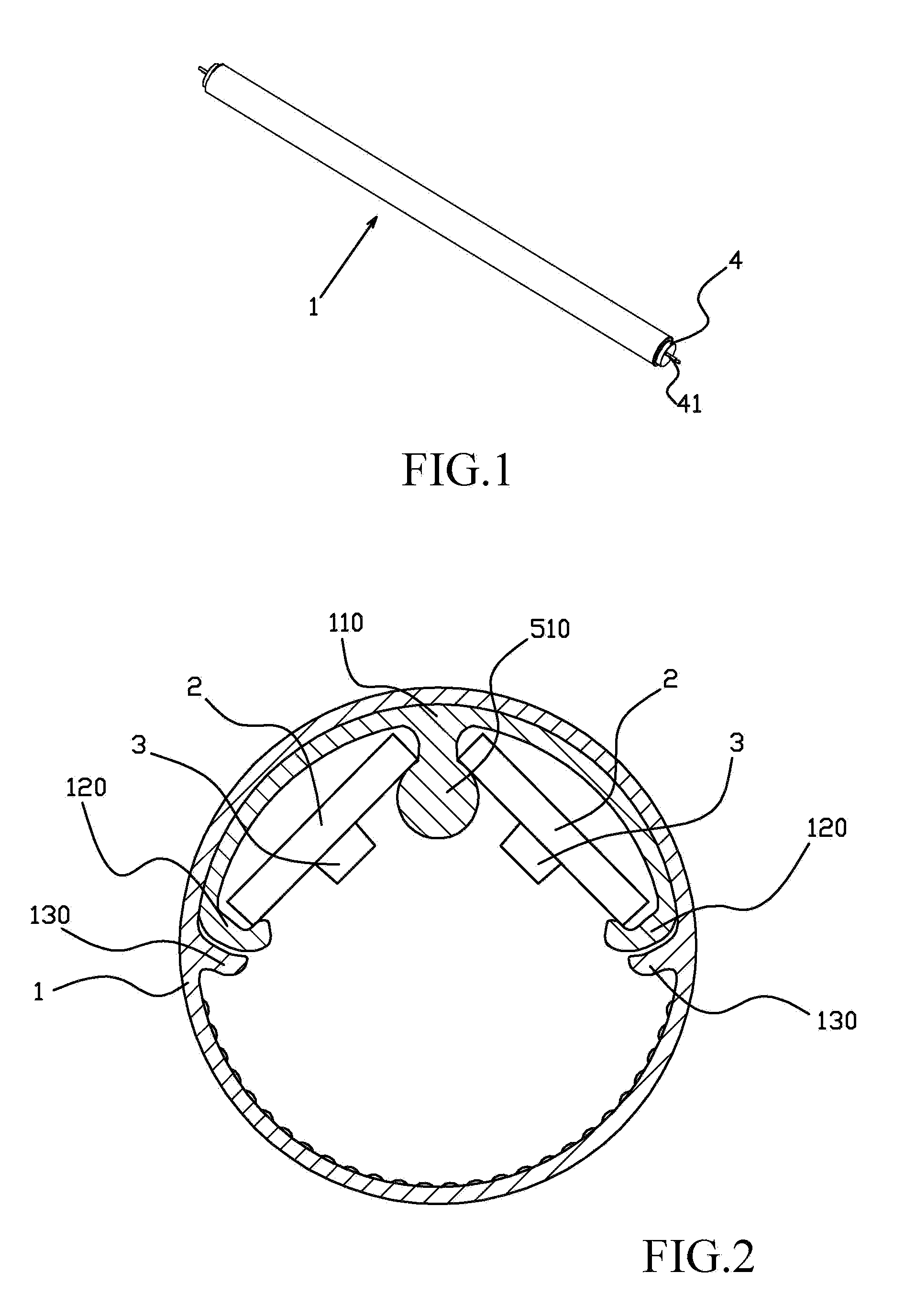
[0055]In the fourth embodiment as shown in FIG. 6, the tube body 1 along its length direction further comprises extra integrated reinforcing ribs 101 on the inner wall thereof. The reinforcing ribs 101 can be symmetrically arranged on the opposite sides of the supporting and positioning ribs, thereby providing higher strength.

fifth embodiment

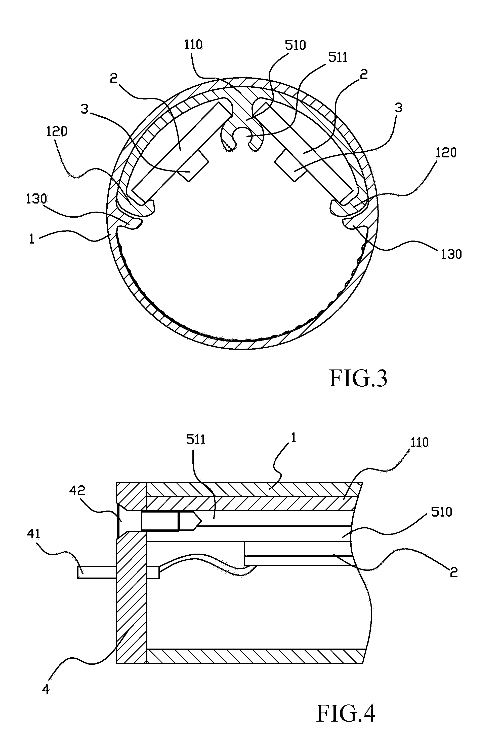
[0056]FIG. 7 illustrates the present invention, wherein the tube body 1 has two groups of two supporting and positioning ribs 121 symmetrically arranged on the back side of the inner wall thereof, each group of supporting and positioning ribs 121 clamps and fixes one circuit board 2, the LED modules 3 on the two circuit boards 2 are lighting simultaneously for higher brightness. Of course, more supporting and positioning ribs 121 can be implemented to mount more circuit boards 2 for higher brightness.

[0057]As a further improvement to the above embodiment, wherein the two symmetrically arranged groups of supporting and positioning ribs 121 allow the two circuit boards 2 fixed to be arranged in a separated reverse V shape (or a “ / \” shape more intuitively) with an acute angle. By this means, during operation, the LED modules on the two circuit boards are lighting simultaneously, their emitting angles are partially overlapped, allowing higher brightness and a wider illuminating angle.

sixth embodiment

[0058]In the present invention shown as FIG. 8, the LED lamp tube further comprises a metal strip 520 mounted in a gap formed between the two groups of supporting and positioning ribs, the metal strip 520 plays multiple roles including supporting the tube 1, preventing the deformation, and conducting and dissipating heat generated by the LED modules.

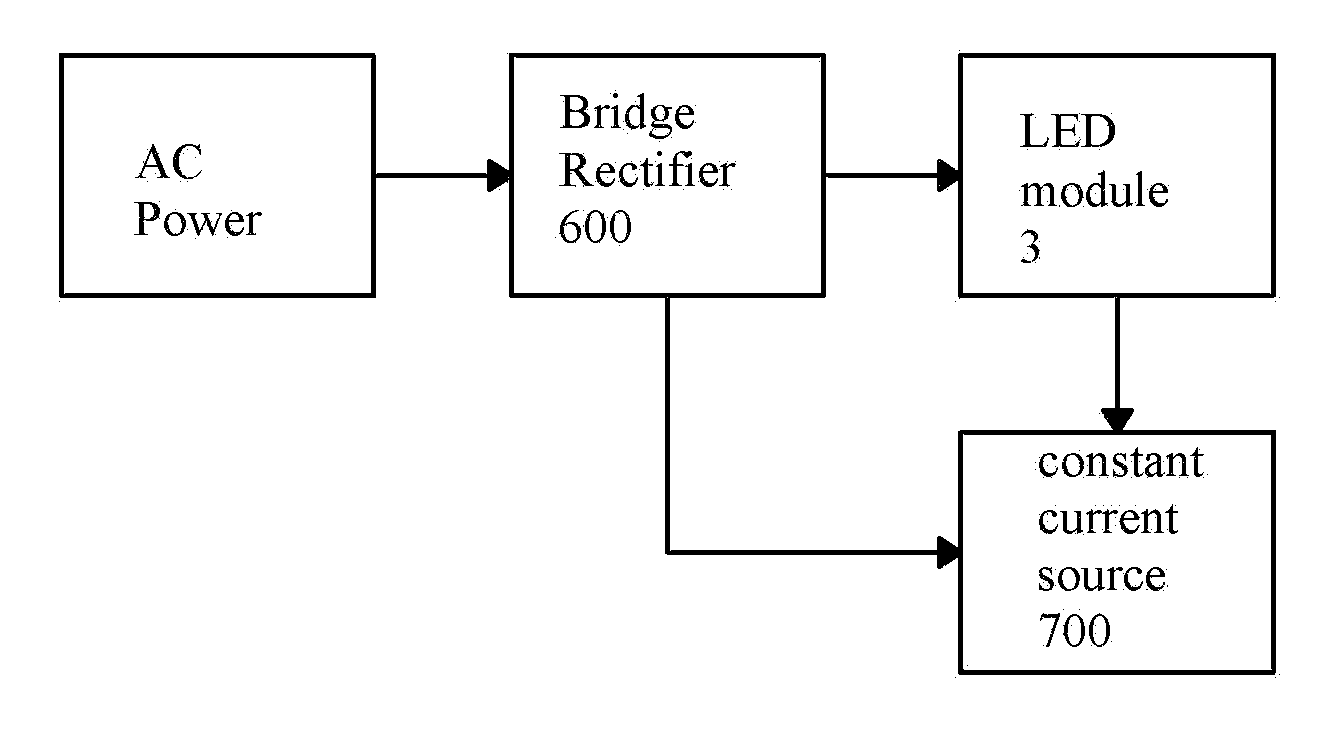
[0059]In the LED lamp tube provided by the present invention, the LED module 3 serves as an illuminant, comprising a plurality of LED units 310 connected in series, according to the different requirements of illumination, the number of parallel connected modules 3 on the circuit board 2 varies, to provide the illumination intensity required.

[0060]As shown by FIG. 9, in a preferred embodiment of the present invention, DC power is used, and for ensuring the stability of the power supplied, the circuit board 2 further comprises a bridge rectifier 600 and a constant current source 700 for the LED module 3, wherein the constant current source...


PUM


Abstract

An LED lamp tube comprises a tube body, at least one circuit board inside the tube body, at lease one LED module on the circuit board, and electrical connectors at the ends of the tube, wherein the tube body is an integrally formed hollow tube, and has at least one group of supporting and positioning ribs on the inner wall thereof along the length direction; the circuit board is fixed by the supporting and positioning ribs; the LED lamp tube disclosed by the present invention has a firm assembly structure with less thermal deformation, and more particularly just like the conventional fluorescent tubes it has a wide light-emitting angle, thereby providing better illumination effects.

Description

BACKGROUND OF THE INVENTION[0001]1. Field of the Invention[0002]The present invention relates in general to an LED lamp, and more particularly to an LED lamp tube.[0003]2. Description of the Related Art[0004]Fluorescent lamps are a common type of illuminating lamps people use, but at present LED lamps have been gradually replacing the conventional fluorescent lamps and becoming the main stream in the market, due to the advantages including environment friendly, energy conservation, longer lifespan, and higher efficiency.[0005]Due to their structural characteristics, as well as in consideration of their relatively high heat production, at present the LED lamp tubes on the market usually have a common structure, in which a circuit board with a plurality of LED units is disposed inside a tube body, and connectors mounted at the two ends of the tube body are plugged into a standardized fluorescent tube fixture for fixing the tube and obtaining electrical power, the heat generated by the...

Claims


Application Information

Patent Timeline
IPC IPC(8): H01K1/62F21V21/00
CPCF21K9/17F21V3/02F21Y2101/02F21Y2103/003F21V29/89H05B33/0803F21V29/506F21V29/74F21Y2111/001F21Y2113/00F21K9/275F21K9/60F21Y2103/10F21Y2107/00F21Y2115/10H05B45/345H05B45/395H05B45/46Y02B20/30
Inventor LEE, KE-CHINLIN, SHIH-CHIANG
Owner ZHONGSHAN WEIQIANG TECH
Why Eureka
Try Eureka