Compressor flowpath

a compressor and flow path technology, applied in the direction of machines/engines, stators, liquid fuel engines, etc., can solve problems such as performance decline, and achieve the effect of reducing the tip clearance of the compressor rotor and reducing the separation of flow

Inactive Publication Date: 2013-08-01
RAYTHEON TECH CORP
View PDF25 Cites 31 Cited by
  • Summary
  • Abstract
  • Description
  • Claims
  • Application Information

AI Technical Summary

Benefits of technology

[0017]In a further non-limiting embodiment of any of the foregoing turbine engines, the turbine engine may include an outer diameter slope angle that is operable to reduce a tip clearance of a compressor rotor, and thereby reduce flow separation.
[0027]In a further non-limiting embodiment of any of the foregoing low pressure compressor, the low pressure compressor may include an outer diameter slope angle that is operable to reduce a tip clearance of a compressor rotor, and thereby reduces flow separation.

Problems solved by technology

Decreasing the number of stages and increasing the rotational speed of the low pressure compressor causes existing flowpath designs to be non-optimal and results in decreased performance when the existing flowpath designs are used.

Method used


Image

  • Compressor flowpath
  • Compressor flowpath
  • Compressor flowpath

Examples


Embodiment Construction

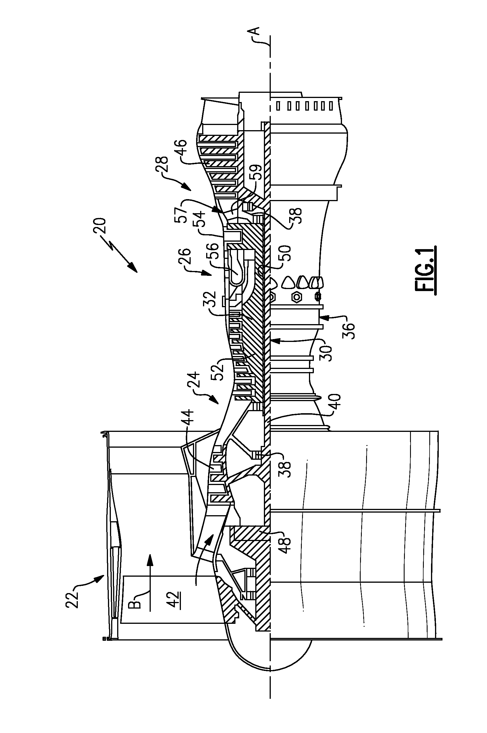
[0032]FIG. 1 schematically illustrates a gas turbine engine 20. The gas turbine engine 20 is disclosed herein as a two-spool turbofan that generally incorporates a fan section 22, a compressor section 24, a combustor section 26 and a turbine section 28. Alternative engines might include, for example, a three-spool design, an augmentor section, and different arrangements of sections, among other systems or features. The fan section 22 drives air along a bypass flowpath while the compressor section 24 drives air along a core flowpath for compression and communication into the combustor section 26 then expansion through the turbine section 28. Although depicted as a turbofan gas turbine engine in the disclosed non-limiting embodiment, it should be understood that the concepts described herein are not limited to use with turbofans as the teachings may be applied to other types of turbine engines.

[0033]The engine 20 generally includes a low speed spool 30 and a high speed spool 32 mounte...


PUM


Abstract

A core flowpath through a low pressure compressor section of a gas turbine engine includes an outer diameter, which has a slope angle relative to an axis defined by the core flowpath. The slope angle is a slope angle that is operable to prevent flow separation of a fluid passing through the core flowpath.

Description

CROSS-REFERENCE TO RELATED APPLICATION[0001]The present application claims priority to U.S. Provisional Application No. 61 / 593001, which was filed on Jan. 31, 2012, and is incorporated herein by reference.TECHNICAL FIELD[0002]The present application relates generally to gas turbine engines, and more particularly to a low pressure compressor flowpath for a gas turbine engine.BACKGROUND OF THE INVENTION[0003]Commercial turbofan engines use low pressure compressors coupled to a fan. Advances in coupling the fan to the low pressure compressor have allowed the compressor to operate at higher speeds and to decrease the number of compressor stages required of the compressor. Decreasing the number of stages and increasing the rotational speed of the low pressure compressor causes existing flowpath designs to be non-optimal and results in decreased performance when the existing flowpath designs are used.SUMMARY OF THE INVENTION[0004]A turbine engine according to an exemplary aspect of the pr...

Claims


Application Information

Patent Timeline
Patent Type & Authority Applications(United States)
IPC IPC(8): F02K3/04F04D29/52
CPCF02K3/04F04D29/681F04D29/522F05D2260/606F05D2220/3217F04D19/028F04D29/547F04D29/682Y02T50/60F02K3/06F04D25/045F04D29/321F04D29/563F05D2220/36
Inventor BRILLIANT, LISA I.ROSE, BECKY E.DONG, YUANBALAMUCKI, STANLEY J.
Owner RAYTHEON TECH CORP
Why Eureka
Try Eureka