
Method for producing a cage of a roller bearing

a cage and roller bearing technology, applied in mechanical equipment, rotary machine parts, transportation and packaging, etc., can solve the problems of increasing production time and cost, unable to be removed, and the raw material cost is higher than necessary with respect to the required strength of the cage, so as to reduce the amount of raw material, and reduce the potential raw material cost

Active Publication Date: 2020-01-14
AB SKF
View PDF18 Cites 0 Cited by
  • Summary
  • Abstract
  • Description
  • Claims
  • Application Information

AI Technical Summary

Benefits of technology

The method achieves a significant reduction in weight and material usage, resulting in a lightweight yet stable cage, suitable for applications like aerospace, with potential weight reduction of up to 70% while maintaining functionality and reducing raw material costs.

Problems solved by technology

This classical production technology means however, that any additional removal of material which is not needed for the strength of the cage (for example to reduce weight) increases production time and cost.
If the material is at a location which cannot be reached by a turning or milling tool, it cannot be removed.
Despite the fact that this material is not needed and removed later it must still be paid for and thus causes cost.
Hence the raw material cost is higher than necessary with respect to the required strength of the cage.

Method used


Image

  • Method for producing a cage of a roller bearing
  • Method for producing a cage of a roller bearing

Examples


Embodiment Construction

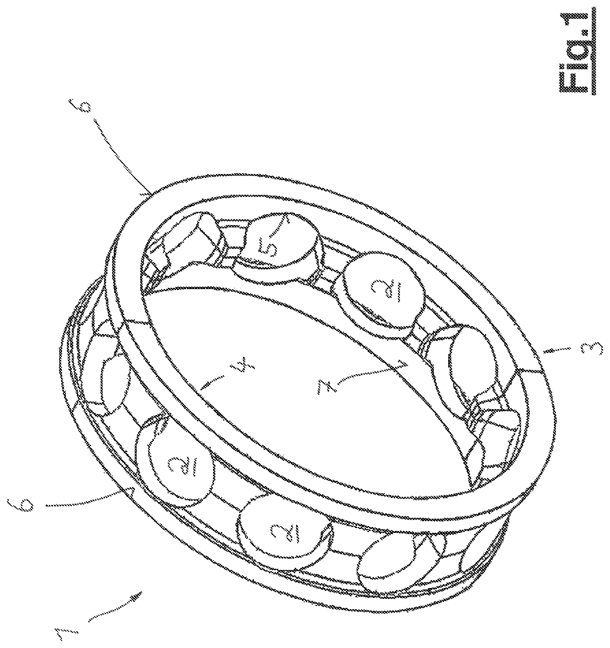
[0036]In FIG. 1 a cage 1 is shown with a basis geometry which is basically hollow-cylindrical. The cage 1 has a plurality of pockets 2 for receiving rolling elements and a radial outer surface 3 as well as a radial inner surface 4. The pockets 2 have a surface 5 for contacting the rolling element (not depicted).

[0037]The process of the production of a cage 1 starts with the definition of the basis geometry of the cage 1 as shown in FIG. 1.

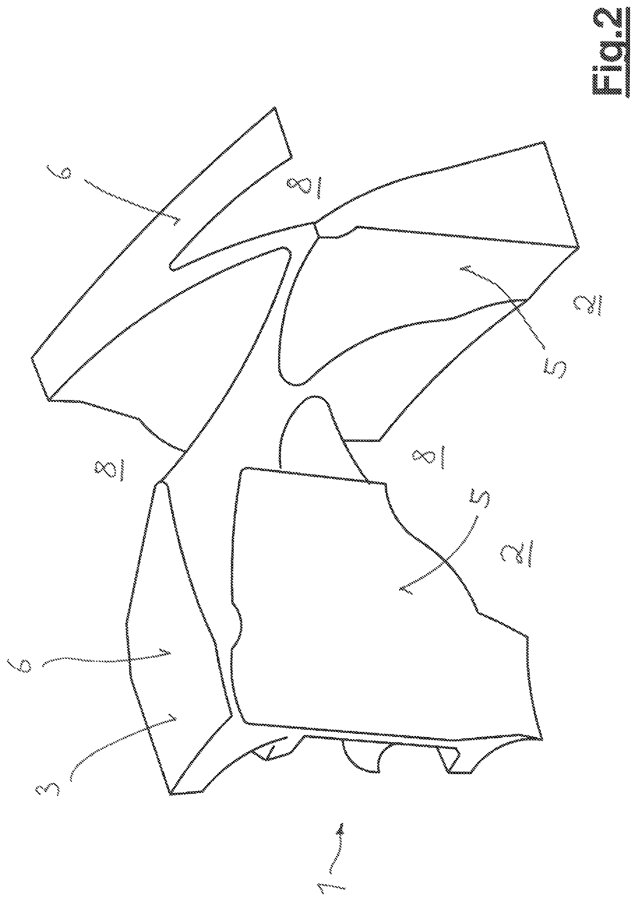
[0038]The next step is to define certain unalterable surfaces. More specifically, a part of the radial outer surface, namely two ring-shaped lateral outer surfaces of the hollow-cylindrical structure of the cage 1, as well as the surfaces 5 of the receiving pockets 5 are such unalterable surfaces; those surfaces must remain to fulfill the function of the cage. The outer surface 6 establishes the guiding of the cage; the surfaces 5 guide each rolling element in the pocket 2.

[0039]Also, a radial inner surface 7 can be defined to be such an unalterabl...


PUM

PropertyMeasurementUnit
angleaaaaaaaaaa
stress distributionaaaaaaaaaa
stressaaaaaaaaaa

Abstract

A method for producing a cage having a body with multiple pockets for rolling elements, the method providing: a) defining a cage basis geometry that provides a radial outer and / or inner surface for contacting a bearing ring and multiple surfaces of the pockets for contacting the rolling elements; b) defining a part of the radial outer and / or inner surfaces as being unalterable surfaces; c) calculating the cage stress distribution when applying a defined stress force from a mathematical model; d) defining cage volume sections where the stress is below a defined threshold; e) removing a part of the volume sections defined according to step d) taking into account the unalterable surfaces according to step b) and the surfaces of the pockets that are unalterable surfaces; f) defining the cage geometry with the removed volume sections; g) manufacturing the cage according to the geometry as defined according to step f).

Description

CROSS REFERENCE TO RELATED APPLICATIONS[0001]This is a United States National Stage Application claiming the benefit of International Application Number PCT / EP2015 / 064505 filed on Jun. 26, 2015 which claims the benefit of British Patent Application 1411891.3 filed on Jul. 3, 2014, both of which are incorporated herein by reference in their entireties.FIELD OF THE INVENTION[0002]The invention relates to a method for producing a cage of a roller bearing, wherein the cage provides a base body with a plurality of pockets for receiving rolling elements.BACKGROUND OF THE INVENTION[0003]Cages of roller bearings are usually rotationally symmetric components that are normally made by stamping or injection molding for medium and high production volumes and by turning and milling for low volume production or if high strength and / or special materials are required. In the latter case, manufacturing starts typically with a tube material that is then turned to the right dimension. The receiving po...

Claims


Application Information

Patent Timeline
Patent Type & Authority Patents(United States)
IPC IPC(8): B21D53/12F16C19/06F16C33/38
CPCB21D53/12F16C33/3806G06F30/23G06F30/17F16C33/385F16C33/3887F16C33/3856F16C19/06F16C2326/47F16C2220/24F16C2326/43F16C33/4605F16C33/4629F16C33/4635F16C33/38B33Y80/00G06F2113/10
Inventor KREBS, PHILIPPPETERS, GILBERTZIEGLER, SEBASTIANZIMMERMANN, GREGORY A.
Owner AB SKF
Learn More