Low profile spinal tethering methods

a low-profile, spinal tethering technology, applied in the direction of prosthesis, osteosynthesis device, surgical staple, etc., can solve the problems of immobility of patients, limited ability of current external braces to correct deformed spines, severe restriction,

Active Publication Date: 2006-09-28
DEPUY SYNTHES PROD INC
View PDF83 Cites 105 Cited by
  • Summary
  • Abstract
  • Description
  • Claims
  • Application Information

AI Technical Summary

Benefits of technology

[0099] One of ordinary skill in the art will appreciate further features and advantages of the invention based on the above-described embodiments. Accordingly, the invention is not to be limited by what has been particularly shown and described, except as indicated by the appended claims. All publications and references cited herein are expressly incorporated herein by reference in their entirety.

Problems solved by technology

These devices, however, resulted in severe restriction and in some cases immobility of the patient.
Furthermore, current external braces have limited ability to correct the deformed spine and typically only prevent progression of the deformity.
While several different rod-based systems have been developed, they tend to be cumbersome, requiring complicated surgical procedures with long operating times to achieve correction.
Further, intraoperative adjustment of rod-based systems can be difficult and may result in loss of mechanical properties due to multiple bending operations.
The rigidity and permanence of rigid rod-based systems can also hinder or prevent growth of the spine and they generally require fusion of many spine levels, drastically reducing the flexibility of the spine.
In addition to excessive rigidity, other drawbacks with current devices include dislodgement and a high profile.

Method used


Image

  • Low profile spinal tethering methods
  • Low profile spinal tethering methods
  • Low profile spinal tethering methods

Examples


Embodiment Construction

[0059] Certain exemplary embodiments will now be described to provide an overall understanding of the principles of the structure, function, manufacture, and use of the devices and methods disclosed herein. One or more examples of these embodiments are illustrated in the accompanying drawings. Those skilled in the art will understand that the devices and methods specifically described herein and illustrated in the accompanying drawings are non-limiting exemplary embodiments and that the scope of the present invention is defined solely by the claims. The features illustrated or described in connection with one exemplary embodiment may be combined with the features of other embodiments. Such modifications and variations are intended to be included within the scope of the present invention.

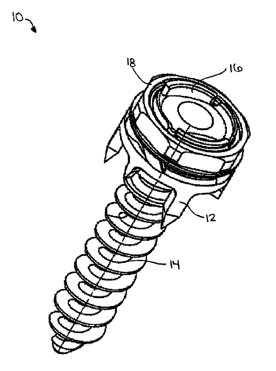
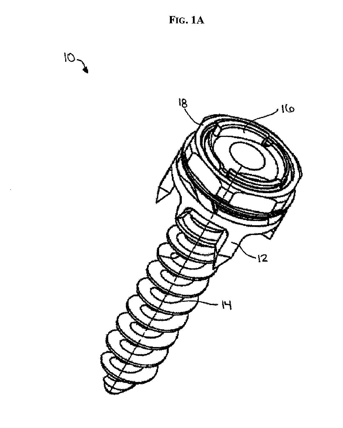
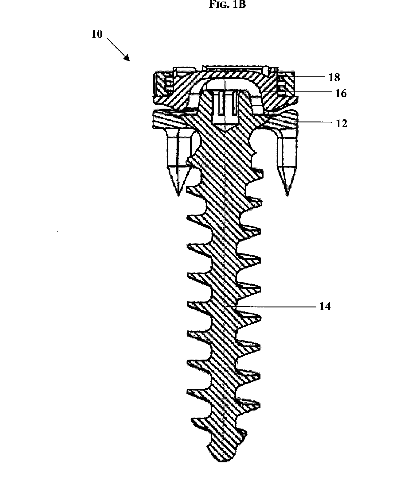
[0060] In one exemplary embodiment, a low-profile spinal anchoring device is provided for receiving a spinal fixation element, such as a tether, therethrough. In use, several spinal anchoring device...


PUM


Abstract

Methods and devices for treating spinal deformities are provided. In one exemplary embodiment, a low-profile spinal anchoring device is provided for receiving a spinal fixation element, such as a tether, therethrough. The device generally includes a staple body that is adapted to seat a spinal fixation element, a fastening element for fixing the staple body to bone, and a locking assembly for coupling a spinal fixation element to the staple body. In one embodiment, the locking assembly includes a washer that is adapted to couple to the staple body such that the spinal fixation is disposed therebetween, and a locking nut that is adapted to engage the staple body to mate the washer to the staple body.

Description

BACKGROUND [0001] Spinal deformities, which include rotation, angulation, and / or curvature of the spine, can result from various disorders, including, for example, scoliosis (abnormal curvature in the coronal plane of the spine), kyphosis (backward curvature of the spine), and spondylolisthesis (forward displacement of a lumbar vertebra). Early techniques for correcting such deformities utilized external devices that apply force to the spine in an attempt to reposition the vertebrae. These devices, however, resulted in severe restriction and in some cases immobility of the patient. Furthermore, current external braces have limited ability to correct the deformed spine and typically only prevent progression of the deformity. Thus, to avoid this need, several rod-based techniques were developed to span across multiple vertebrae and force the vertebrae into a desired orientation. [0002] In rod-based techniques, one or more rods are attached to the vertebrae at several fixation sites to...

Claims


Application Information

Patent Timeline
Patent Type & Authority Applications(United States)
IPC IPC(8): A61F2/30
CPCA61B17/0642A61B2017/564A61B17/1655A61B17/1671A61B17/70A61B17/701A61B17/7022A61B17/8695A61B17/8877A61B17/8894A61B17/92A61B2017/0648A61B2017/867A61B17/704A61B17/1604A61B17/7053A61B2017/567A61B2017/681
Inventor SERHAN, HASSAN A.SLIVKA, MICHAEL A.HANNEN, MATHEWNEWTON, PETERNILSSON, MICHAEL
Owner DEPUY SYNTHES PROD INC
Why Eureka
Try Eureka