Percussion detecting apparatus and electronic percussion instrument

a percussion instrument and detecting device technology, applied in the field of percussion detecting devices and electronic percussion instruments, can solve the problems of difficult attachment of light transmitters to low durability of the portion of the percussion surface parts where light transmitters were attached, and the acoustic percussion instrument provides a different percussion feeling than the acoustic percussion instrument, etc., to achieve excellent percussion feeling, suppress excessive resilience of the percussion surface, and increase the interest of practi

Inactive Publication Date: 2006-10-05
YAMAHA CORP
View PDF7 Cites 50 Cited by
  • Summary
  • Abstract
  • Description
  • Claims
  • Application Information

AI Technical Summary

Benefits of technology

[0022] With the arrangement of the second aspect of the present invention, it is possible to provide the same advantageous effects as provided by the percussion detecting apparatus according to the first aspect of the present invention.
[0023] Preferably, the pattern of light radiation by the light radiating part changes according to a beat position on the percussion surface.
[0024] With the arrangement of this preferred embodiment, beat positions can be visually recognized, which further serves for percussion practice and increases interest in the practice.
[0025] To attain the first object, in a third aspect of the present invention, there is provided a percussion detecting apparatus comprising a percussion surface part formed of an air-permeable material and having a light transmitting property, the percussion surface part including a percussion surface, a support part that supports the percussion surface part, a detecting device that detects a beat applied to the percussion surface of the percussion surface part and outputs a beat signal indicative of the sensed beat, and a percussion pattern indicating device that performs visual indication corresponding to a percussion pattern of the beat applied to the percussion surface, at least through the percussion surface, based on the beat signal output from the detecting device, wherein the percussion pattern indicating device includes a light radiating part that is resilient and radiates light, the light radiating part is disposed on an opposite side from the percussion surface of the percussion surface part such that the light radiating part is visible through the percussion surface part from a side toward the percussion surface, and when the percussion surface of the percussion surface part is beaten, the light radiating part is pressed by the percussion surface part and is resiliently deformed, thereby applying a reaction force to the percussion surface part and changing a pattern of light radiation by the light radiating part, whereby visual indication corresponding to the percussion pattern is performed.
[0026] With the arrangement of the third aspect of the present invention, a percussion pattern is visually indicated by resilient deformation of the light radiating part, and at the same time excessive resilience of the percussion surface is suppressed by generation of a reaction force, which makes percussion feeling closer to that obtained from an acoustic percussion instrument. Therefore, it is possible not only to provide excellent percussion feeling by the simple construction, but also to visually indicate a percussion pattern of a beat applied to the percussion surface, so as to serve for percussion practice as well as to make the percussion practice enjoyable.
[0027] Preferably, the pattern of light radiation by the light radiating part changes according to a beat position on the percussion surface.

Problems solved by technology

However, percussion feeling provided by the electronic percussion instrument is quite different from that provided by an acoustic percussion instrument.
H10-198354, since the percussion surface part is formed of a mesh material, it is not easy to attach the light transmitter to the percussion surface part.
Even if the light transmitter could be successfully attached to the mesh material, durability of the portion of the percussion surface part where the light transmitter was attached would be low, and there is a fear that percussion feeling and sensing might be adversely affected by changes in the pattern of vibration of the mesh material during application of percussion.
For this reason, in actuality, it has been impossible even to think of proving the percussion pattern indicating function in the percussion detecting apparatuses disclosed in Japanese Laid-Open Patent Publications (Kokai) No.
Further, even the percussion detecting apparatuses having the percussion surface part formed of the mesh material do not provide percussion feeling which perfectly matches that obtained from an acoustic percussion instrument, but tend to provide percussion feeling with slightly excessive resilience.
Furthermore, these percussion detecting apparatuses having the percussion surface part formed of the mesh material must be formed into a drum shape, and are low in the degree of freedom of design.

Method used


Image

  • Percussion detecting apparatus and electronic percussion instrument
  • Percussion detecting apparatus and electronic percussion instrument
  • Percussion detecting apparatus and electronic percussion instrument

Examples


first embodiment

[0090] In the following, the present invention will be described with reference to FIGS. 1 to 4C.

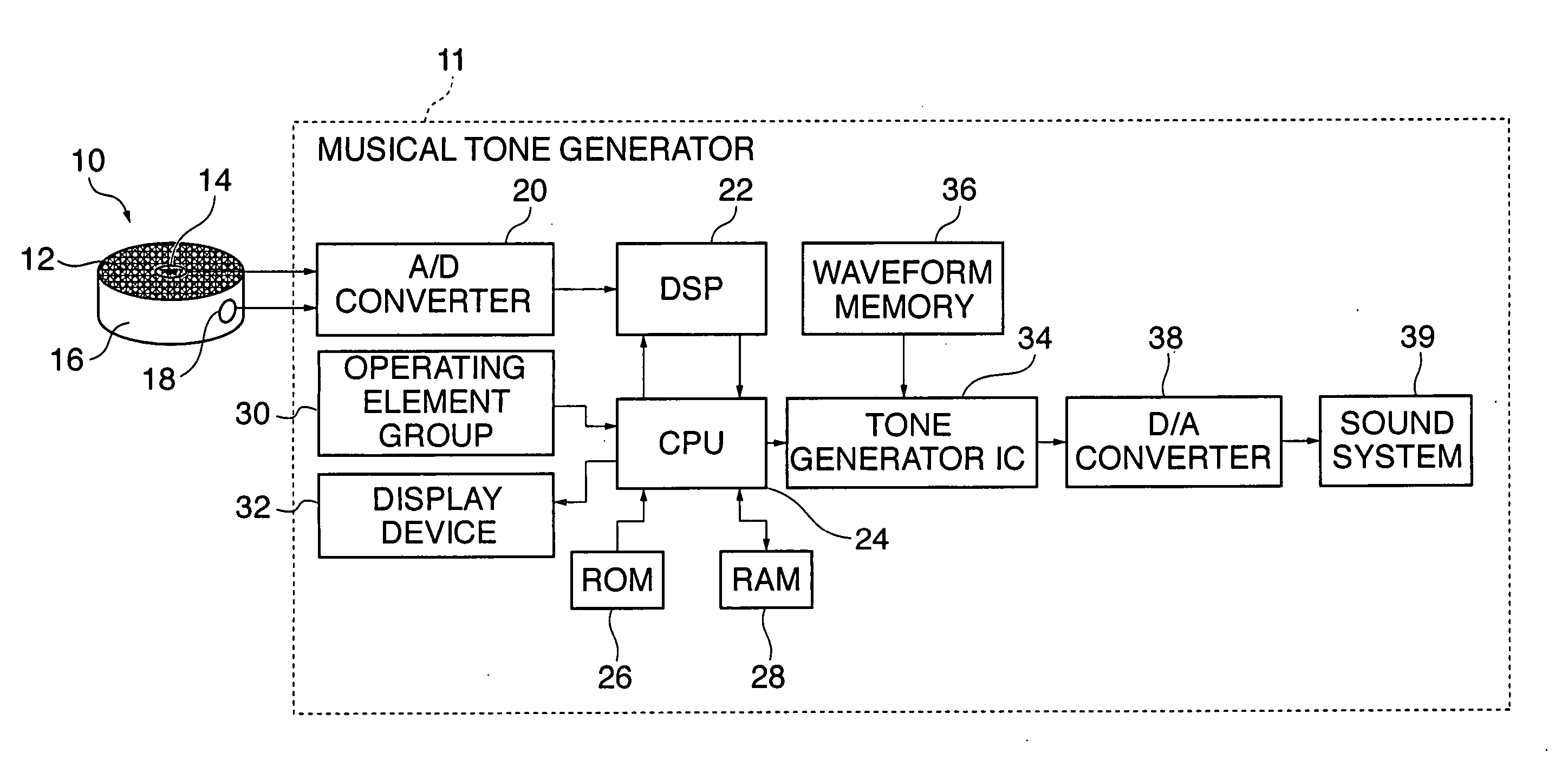
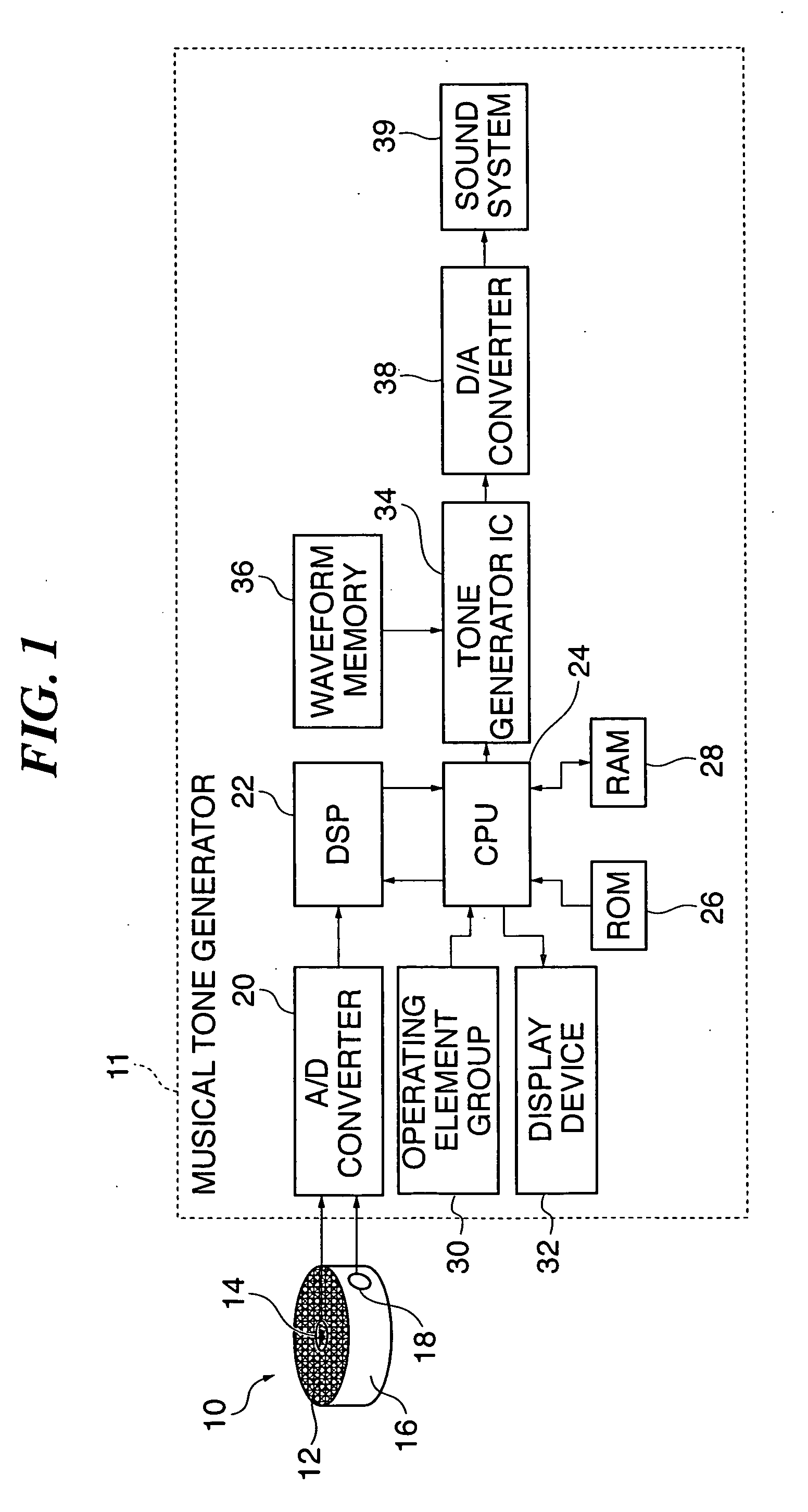
[0091]FIG. 1 is a block diagram of an electronic percussion instrument apparatus to which is applied a percussion detecting apparatus according to the first embodiment. This electronic percussion instrument apparatus is formed by electrically connecting the percussion detecting apparatus 10 and a musical tone generator 11.

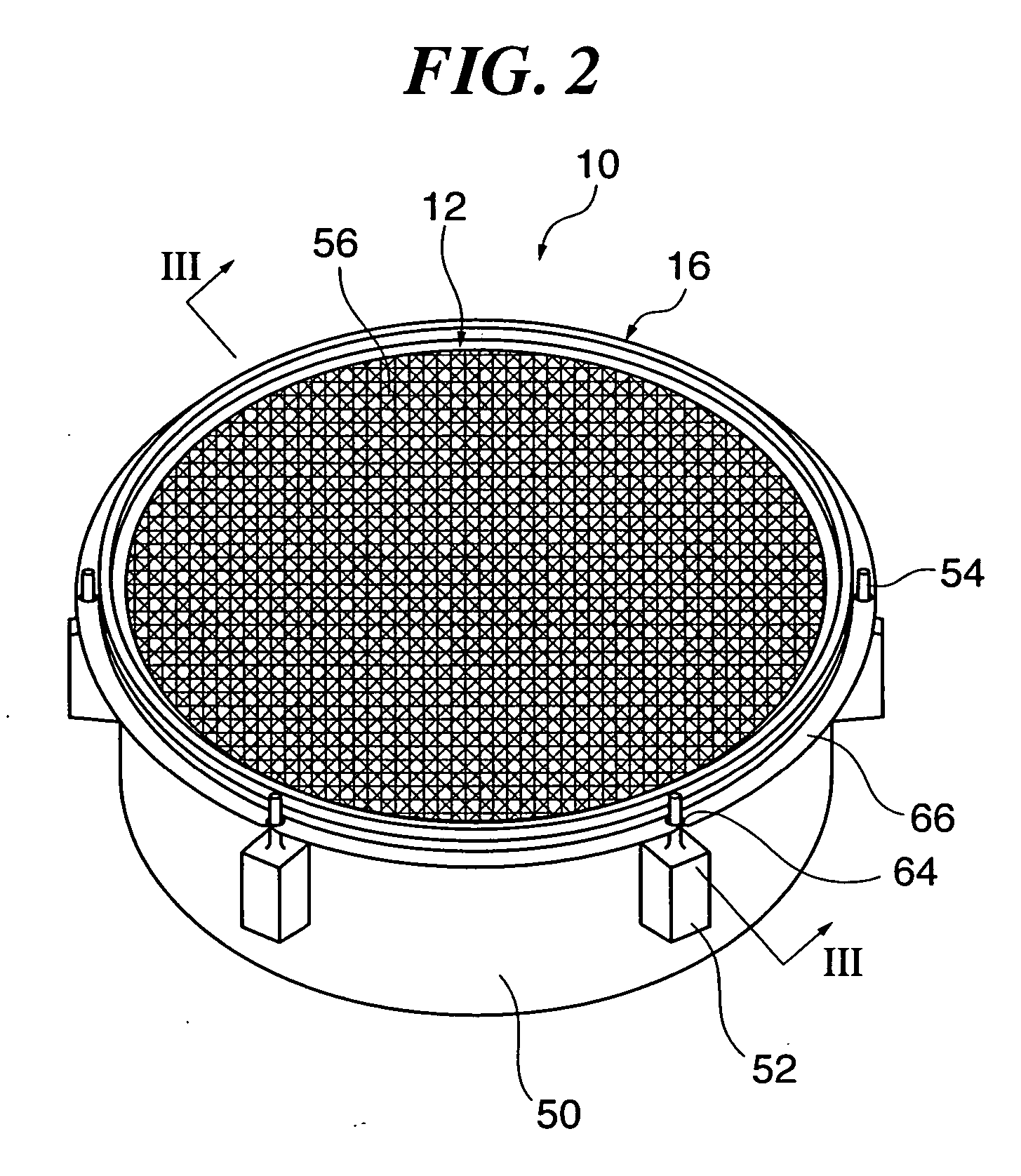
[0092] The percussion detecting apparatus 10 includes a head sensor 14 that detects beats applied to a head 12 having a percussion surface 12a formed of an air-permeable material (specifically, an air-permeable mesh material, for example), as described in detail hereinafter, and a rim shot sensor 18 that detects beats applied to a rim 16.

[0093] The musical tone generator 11 is comprised of a CPU 24 controlling the overall operation of the musical tone generator 11, and an operating element group 30, a display device 32, a read-only memory (ROM) 26, and a random access...

second embodiment

[0130] Next a description will be given of the present invention.

[0131] The second embodiment is distinguished from the first embodiment in that a light radiating part 140 is provided in place of the light radiating part 40 in the first embodiment. The other components are identical to the corresponding ones in the first embodiment.

[0132]FIG. 5A is a plan view of the light radiating part 140 of a percussion detecting apparatus according to the second embodiment. FIG. 5B is a cross-sectional view taken on line VB-VB in FIG. 5A, and FIG. 5C a cross-sectional view taken on line VC-VC in FIG. 5A.

[0133] The light radiating part 140 of the percussion detecting apparatus according to the present embodiment is comprised of a tube body 81, and two light emitting units 82. Similarly to the light radiating part 40, the light radiating part 140 is formed into an annular shape as viewed in plan view, and has an Ω-shaped cross section formed by the tube body 81 and flange parts 81a, as shown in...

third embodiment

[0141] Next, a description will be given of the present invention.

[0142] The third embodiment is distinguished from the first embodiment in that a means for generating a reaction force against a beat applied to the head 12 is provided in the vicinity of the outer periphery of the head 12 separately from the light radiating part. Further, the light radiating part 40 is formed to be softer than in the first embodiment so as to reduce a reaction force generated by the light radiating part 40 itself. The other components are identical to the corresponding ones in the first embodiment.

[0143]FIG. 7A is a fragmentary cross-sectional view of a hollow cylindrical drum shell of a percussion detecting apparatus according to the third embodiment. FIG. 7B is a partial plan view of the hollow cylindrical drum shell with the head 12 removed therefrom.

[0144] The drum shell 50 has an upper part thereof integrally formed with engaging projections 50a arranged at equal space intervals at a plurality...


PUM


Abstract

A percussion detecting apparatus and an electronic percussion instrument, which are capable of not only providing excellent percussion feeling, but also visually indicating a percussion pattern of a beat applied to a percussion surface, so as to serve for percussion practice as well as to increase interest in the percussion practice. A head of the percussion detecting apparatus is formed of an air-permeable material and has a light transmitting property. The head includes a percussion surface. A drum shell supports the head. A head sensor detects a beat applied to the percussion surface of the head and outputs a beat signal indicative of the sensed beat. A light radiating part is disposed on an opposite side from the percussion surface of the head so as to perform visual indication corresponding to a percussion pattern of the beat applied to the percussion surface, at least through the percussion surface, based on the beat signal output from the head sensor.

Description

BACKGROUND OF THE INVENTION [0001] 1. Field of the Invention [0002] The present invention relates to a percussion detecting apparatus that detects a beat signal for causing a drum device or the like to electronically generate a musical tone, according to a beat applied to a percussion surface, and an electronic percussion instrument. [0003] 2. Description of the Related Art [0004] Conventionally, an electronic percussion instrument, such as an electronic drum, generally has a percussion surface part formed by a rubber pad (see e.g. Japanese Laid-Open Patent Publication (Kokai) No. 2000-47666). However, percussion feeling provided by the electronic percussion instrument is quite different from that provided by an acoustic percussion instrument. [0005] On the other hand, there have also been proposed percussion detecting apparatuses having a percussion surface part formed of a mesh material (see Japanese Laid-Open Patent Publications (Kokai) No. H10-20854 and No. H10-198354). These pe...

Claims


Application Information

Patent Timeline
Patent Type & Authority Applications(United States)
IPC IPC(8): G10H3/06
CPCG10H1/0008G10H3/06G10H2220/311G10H2220/066G10H3/146Y10S84/12
Inventor MISHIMA, JUNICHI
Owner YAMAHA CORP
Why Eureka
Try Eureka