Supercharge Your Innovation With Domain-Expert AI Agents!

Methods and apparatus to DC couple LVDS driver to CML levels

a technology of dc coupler and driver, applied in the direction of logic circuit coupling arrangement, pulse technique, reliability increasing modification, etc., can solve the problem of difficult dc coupler of lvds transceiver to a cml transceiver, and achieve the effect of widening the customer bas

Inactive Publication Date: 2006-10-05
ALTERA CORP
View PDF4 Cites 8 Cited by
  • Summary
  • Abstract
  • Description
  • Claims
  • Application Information

AI Technical Summary

Benefits of technology

The invention provides a way for an LVDS-like transmitter to communicate with a CML receiver using a DC coupling method. By replacing the common mode voltage source with a resistive pulldown, the transmitter can interface with the receiver in a more efficient way. The resistive pulldown can also be programmed to meet the requirements of different customers, making it easier to support a wide range of applications. Overall, this advancement expands the customer base that the transmitter can support.

Problems solved by technology

Ordinarily, it is difficult for an LVDS transceiver to DC couple to a CML transceiver because both of the transceivers would operate at different DC voltage levels.
However there is overhead required for AC coupling, such as coupling capacitors for blocking the DC voltage levels, and special signal encoding to prevent drifting of the DC voltage level.

Method used


Image

  • Methods and apparatus to DC couple LVDS driver to CML levels
  • Methods and apparatus to DC couple LVDS driver to CML levels
  • Methods and apparatus to DC couple LVDS driver to CML levels

Examples


Embodiment Construction

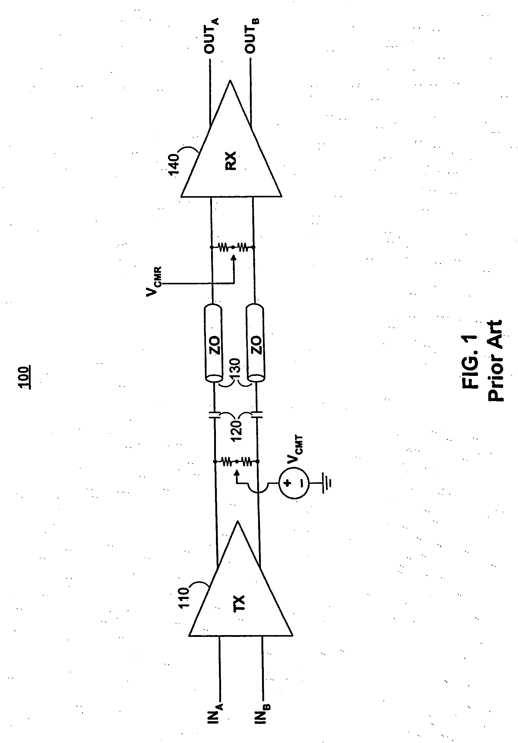
[0016]FIG. 1 shows a simplified block diagram 100 of a typical AC coupled transmitter to receiver link. Differential transmitter 110 is connected through two AC coupling capacitors 120 over transmission lines 130 to differential receiver 140. Transmitter 110 may be an LVDS transmitter. An LVDS transmitter may have a common mode voltage VCMT that may be terminated to a voltage level that is approximately half of the supply voltage. Receiver 140 may be a CML receiver. A CML receiver may be terminated to a voltage level that is approximately equal to the supply voltage. In order to connect the LVDS transmitter 110 with the CML receiver 140, coupling capacitors 120 may be used to AC couple the transmitter and receiver allowing each to operate at its own DC level.

[0017] LVDS transceivers are preferred over CML transceivers in PLDs because of their lower power consumption, more symmetrical single ended outputs, and better AC coupling support. However, in accordance with the present inven...


PUM


Abstract

Circuitry and methods are provided for an LVDS-like transmitter that may be able to DC couple to a receiver having a CML termination scheme. Replacing the common mode voltage source of an LVDS transmitter with a resistive pulldown to ground may allow the transmitter to interface in a DC coupled fashion with a CML receiver. Further, the resistive pulldown may be programmable. This LVDS-like transmitter may be able to support a wider customer base by allowing it to DC couple to a wider range of termination voltage levels, such as CML termination voltage levels.

Description

BACKGROUND OF THE INVENTION [0001] This invention relates to a low-voltage differential signaling (LVDS) buffer design that enables operation at current mode logic (CML) voltage levels. [0002] LVDS and CML are two standards commonly used for differential signal transmission. These standards are especially common in the field of high-speed serial (HSS) interfaces. While each standard has its own advantages and disadvantages, LVDS is generally preferable to CML because it consumes less power due to its lower quiescent DC current. LVDS is also preferable to CML because its implementation has a more standard specification and is less vendor specific. [0003] Ordinarily, it is difficult for an LVDS transceiver to DC couple to a CML transceiver because both of the transceivers would operate at different DC voltage levels. Thus, typically when coupling LVDS and CML transceivers, only AC coupling may be used. [0004] AC coupling decouples or blocks the DC voltage values at the transmitter (TX...

Claims


Application Information

Patent Timeline
Patent Type & Authority Applications(United States)
IPC IPC(8): H03K19/094
CPCH03K19/017545
Inventor WONG, WILSONHOANG, TIM TRISHUMARAYEV, SERGEY YURYEVICHPATEL, RAKESH H.MAANGAT, SIMARDEEP
Owner ALTERA CORP
Features
  • R&D
  • Intellectual Property
  • Life Sciences
  • Materials
  • Tech Scout
  • Unparalleled Data Quality
  • Higher Quality Content
  • 60% Fewer Hallucinations
Learn More