Planar light source device, display device, terminal device, and method for driving planar light source device

a technology of display device and planar light source, which is applied in the direction of static indicating device, lighting and heating apparatus, instruments, etc., can solve the problems of insignificant grayscale inversion, poor display performance, and inability to improve visual characteristics, so as to improve response speed and prevent abnormal flashing during radiation angle switching.

Inactive Publication Date: 2006-10-05
NEC LCD TECH CORP
View PDF7 Cites 15 Cited by
  • Summary
  • Abstract
  • Description
  • Claims
  • Application Information

AI Technical Summary

Benefits of technology

[0016] An object of the present invention is to provide a planar light source device capable of switching the range of radiation angles, wherein the planar light source device can prevent abnormal flashing when the radiation angle is switched; to provide a display device that is equipped with this planar light source device and is capable of switching the range of viewing angles; to provide a terminal device in which this display device is installed; and to provide a method for driving the planar light source device.

Problems solved by technology

Energy consumption can be reduced in the reflective type, since it can utilize external light in the display device, but contrast and other aspects of display performance are inferior compared to the transmissive type.
This problem of grayscale inversion was relatively insignificant in mobile telephones and other terminal devices when the display content consisted mainly of telephone numbers and other characters.
The visual characteristics do not improve at this time, but when the display need only be correctly recognized by a single user, the viewing angle characteristics resemble those of a conventional TN liquid crystal, and a user can use the display without the display being correctly recognized by another person.
As a result, light is not transmitted to positions where the display unit is viewed at an angle to the left or right in the horizontal direction, the screen is darkened when viewed from such a position, and it becomes impossible to recognize the displayed content.
However, in the aforementioned first and second conventional viewing-angle-controlled liquid crystal display devices, there is abnormal flashing that causes discomfort for the user when the switch is made from narrow-angle display having a narrow range of viewing angles to wide-angle display having a wide range of viewing angles.

Method used


Image

  • Planar light source device, display device, terminal device, and method for driving planar light source device
  • Planar light source device, display device, terminal device, and method for driving planar light source device
  • Planar light source device, display device, terminal device, and method for driving planar light source device

Examples


first embodiment

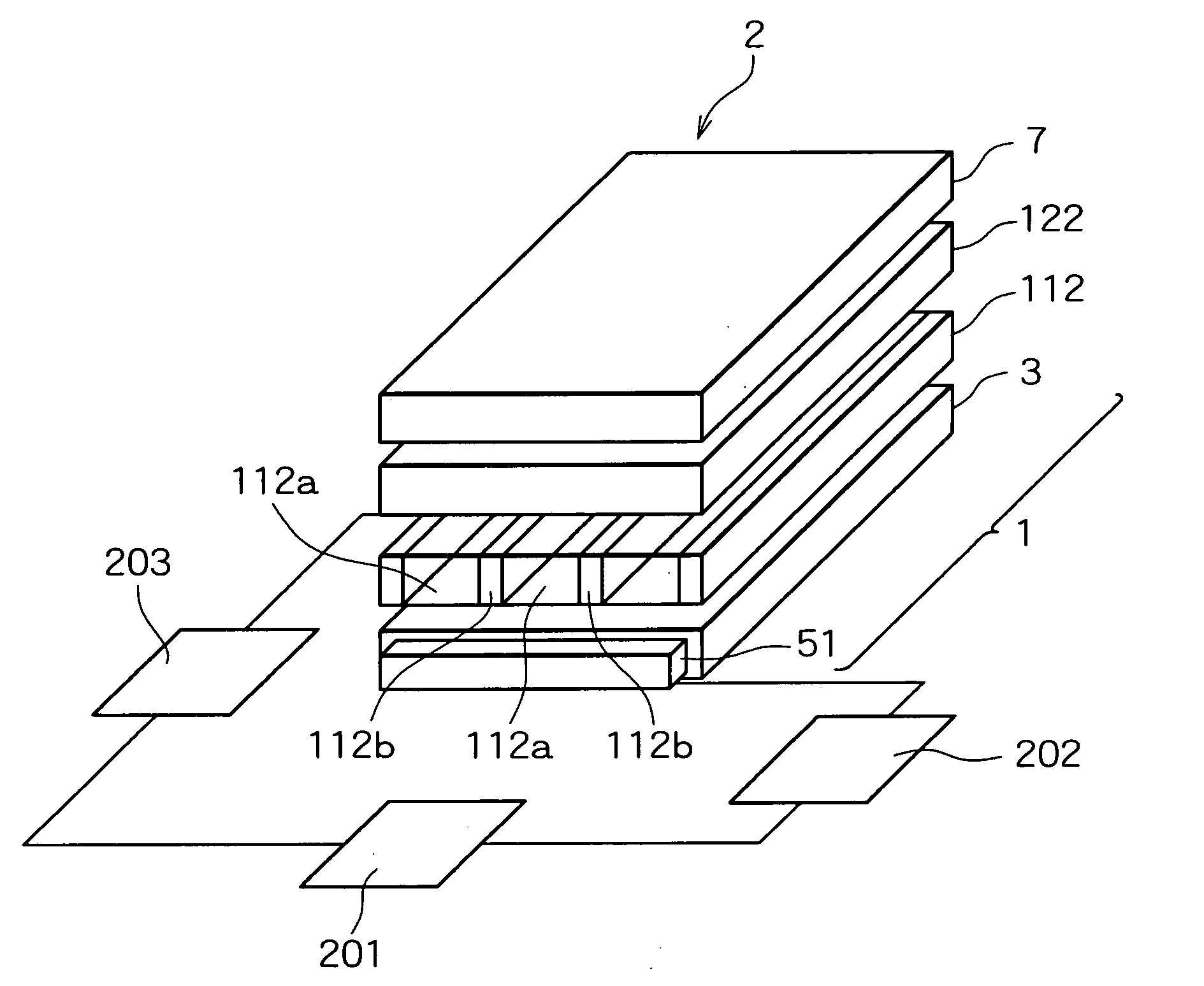
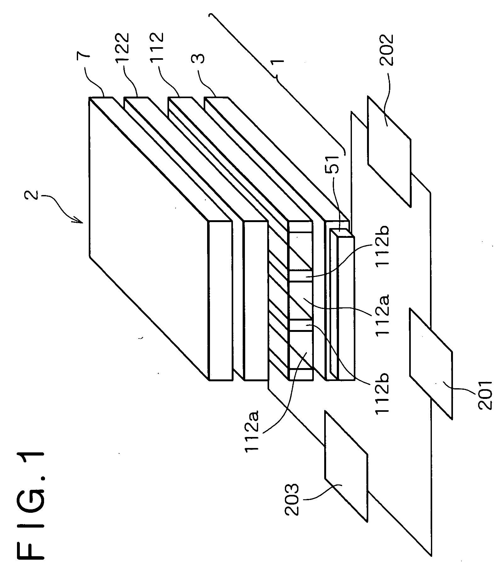
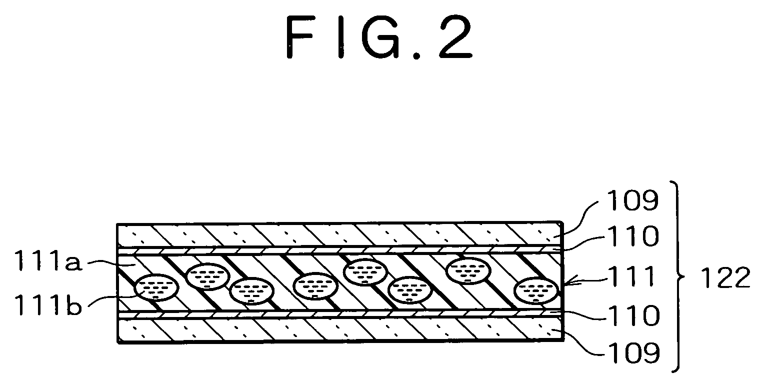
[0078] Therefore, in the present invention, a control circuit for controlling the operation of the light source and the transparent / scattering state switching element is provided in the display device in order to overcome the abovementioned problems. The planar light source device, display device, terminal device, and method for driving a planar light source device according to embodiments of the present invention will be described in detail hereinafter with reference to the accompanying drawings. The planar light source device, display device, terminal device, and method for driving a planar light source device according to the present invention will first be described. FIG. 1 is a perspective view showing the display device according to the present embodiment, FIG. 2 is a sectional view showing the transparent / scattering state switching element that is a constituent element of the display device, and FIG. 3 is a perspective view showing a terminal device in which the display devic...

third embodiment

[0120] The operation of the display device according to the present embodiment thus configured, specifically, the method for driving the planar light source device according to the present embodiment, will next be described. FIGS. 10A through 10E are timing charts showing the state change when the display device according to the present invention is switched from narrow-angle display to wide-angle display, wherein time is plotted on the horizontal axis of each chart, FIG. 10A has the output voltage of the drive circuit for the transparent / scattering state switching element plotted on the vertical axis, FIG. 10B has the haze of the transparent / scattering state switching element plotted on the vertical axis, FIG. 10C has the output current of the light source drive circuit plotted on the vertical axis, FIG. 10D has the intensity of the light source plotted on the vertical axis, and FIG. 10E has the frontal luminance of the display device plotted on the vertical axis.

[0121] When the di...


PUM

PropertyMeasurementUnit
response timeaaaaaaaaaa
transparentaaaaaaaaaa

Abstract

A display device having an optical waveguide and a light source are provided, and also having a louver, a transparent / scattering state switching element, and a transmissive liquid crystal display panel provided in the order indicated on the side of the light-emitting surface of the optical waveguide. The transparent / scattering state switching element switches between a state for scattering the incident light and a state for transmitting the light without scattering. The light source drive circuit causes the transparent / scattering state switching element to transfer from the transparent state to the scattering state, and when the viewing angle range of the display is switched from narrow to wide, the intensity of the light source is gradually increased in conjunction with the transition state of the transparent / scattering state switching element. By this configuration, abnormal flashing during switching of the radiation angle can be prevented in a planar light source device that is capable of switching the radiation angle range.

Description

BACKGROUND OF THE INVENTION [0001] 1. Field of the Invention [0002] The present invention relates to a planar light source device capable of switching the radiation angle of illuminating light, to a display device provided with this planar light source device and capable of switching the angle range of visibility, to a terminal device equipped with this display device, and to a method for driving the planar light source device. [0003] 2. Description of the Related Art [0004] Because of their thin profile, light weight, small size, low energy consumption, and other advantages, display devices that use liquid crystals have been widely deployed and used in a range of devices that includes monitors, televisions (TV: Television), and other large terminal devices; notebook-type personal computers, cash dispensers, vending machines, and other mid-sized terminal devices; and personal TVs, PDAs (Personal Digital Assistance: personal information terminal), mobile telephones, mobile gaming dev...

Claims


Application Information

Patent Timeline
Patent Type & Authority Applications(United States)
IPC IPC(8): F21V7/04F21S2/00F21V8/00F21Y101/02G02F1/133G02F1/13357G09G3/20G09G3/34G09G3/36H05B37/02
CPCG02F1/1323G02F1/133606G02F1/133524
Inventor UEHARA, SHINICHISUMIYOSHI, KENOKUMURA, FUJIO
Owner NEC LCD TECH CORP
Why Eureka
Try Eureka