Magnetic recording medium and magnetic recording device

Inactive Publication Date: 2006-10-05
SHOWA DENKO KK
View PDF7 Cites 36 Cited by
  • Summary
  • Abstract
  • Description
  • Claims
  • Application Information

AI Technical Summary

Benefits of technology

[0026] According to the present invention, the magnetic recording device includes the magnetic recording medium which strikes a balance between the writing performance and the res

Problems solved by technology

Since the main recording layer has large perpendicular magnetic anisotropy, magnetization of the main recording layer is not ea

Method used


Image

  • Magnetic recording medium and magnetic recording device
  • Magnetic recording medium and magnetic recording device
  • Magnetic recording medium and magnetic recording device

Examples


first embodiment

(1) First Embodiment

[0037] Next, a description is given of a magnetic recording medium according to an embodiment of the present invention in detail, following a production process thereof.

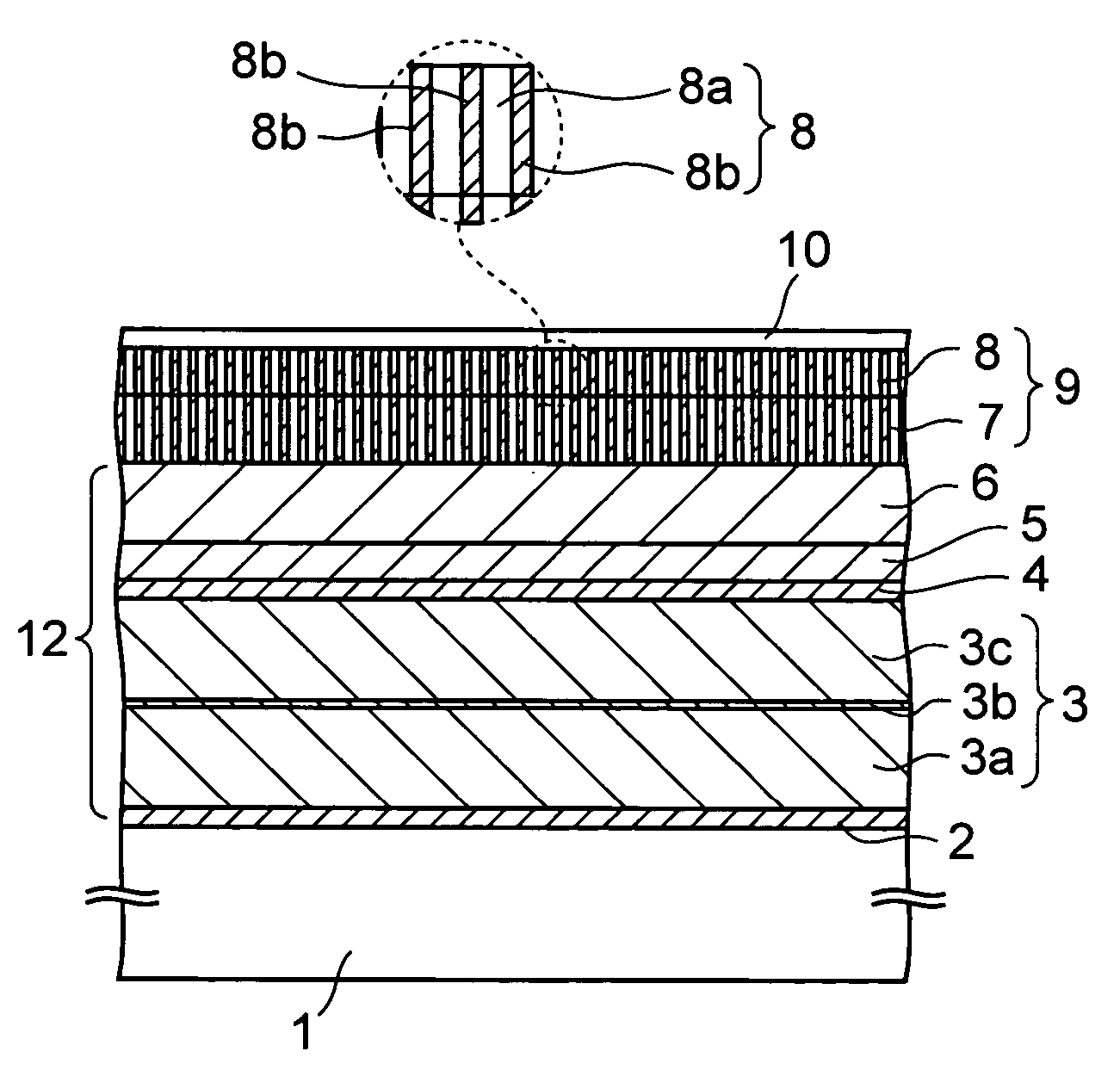
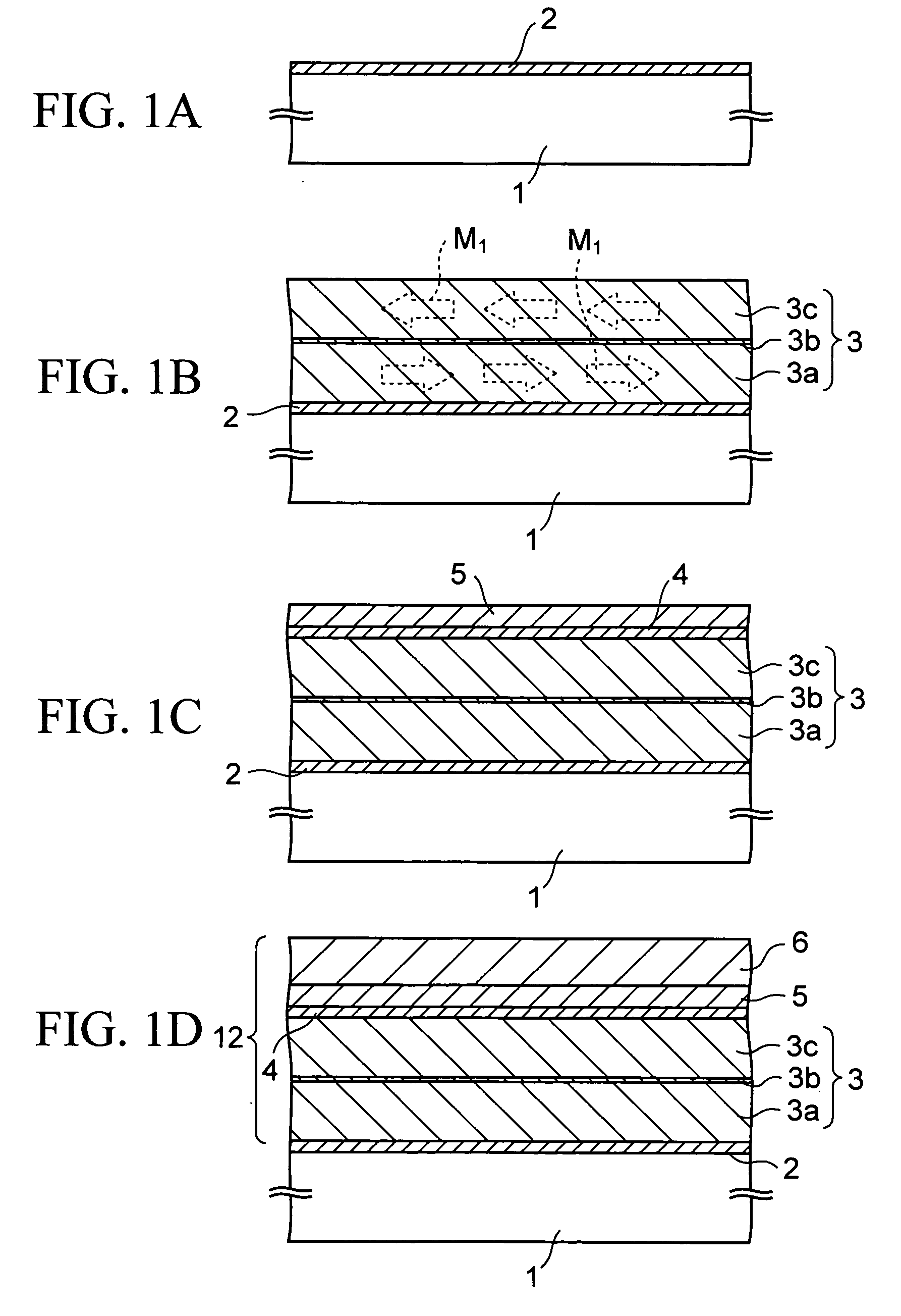
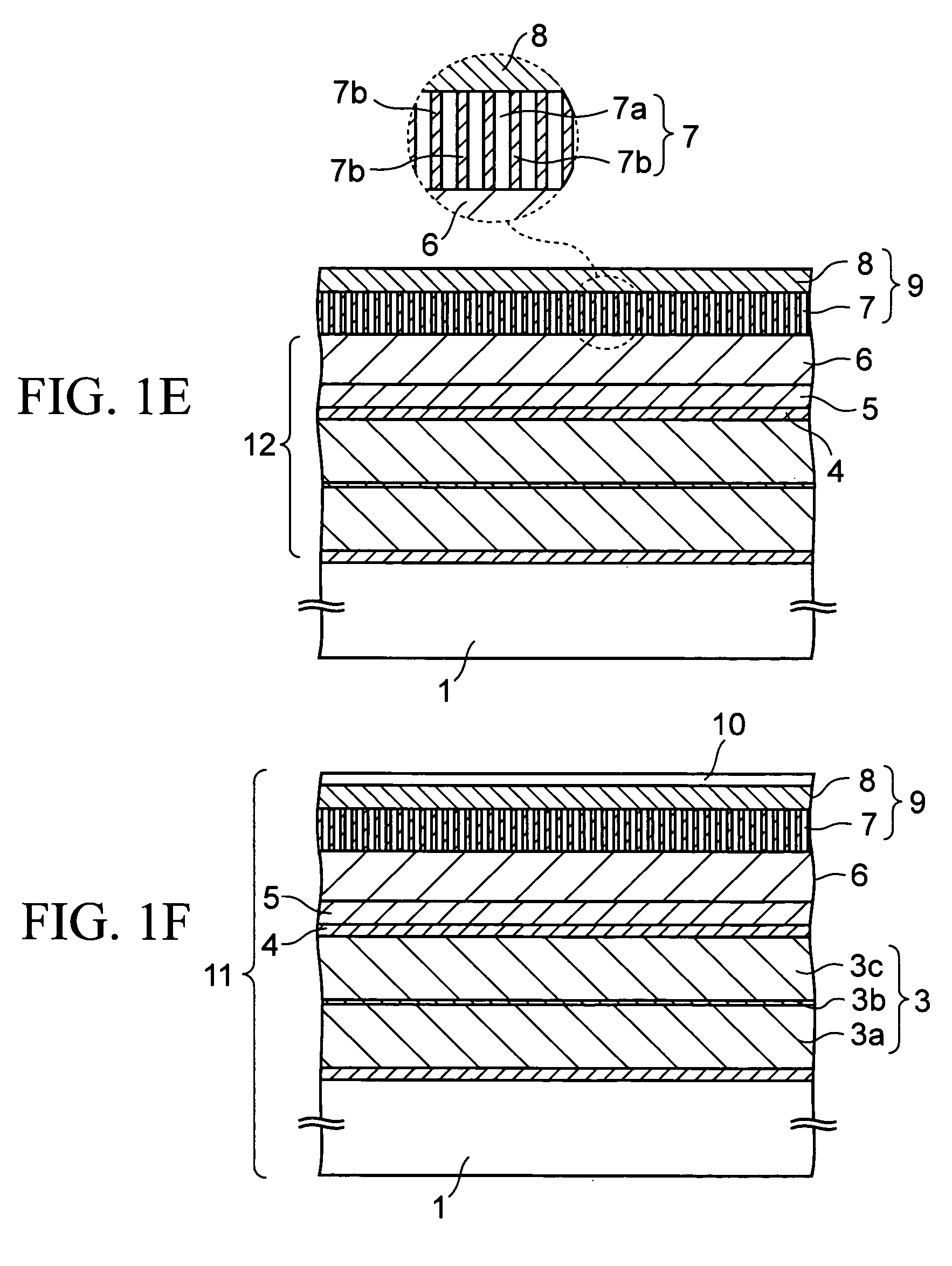
[0038]FIGS. 1A to 1F are cross-sectional views of the magnetic recording medium according to the first embodiment in the course of production. This magnetic recording medium is a perpendicular magnetic recording medium in which the direction of magnetization in a recording layer is directed to the perpendicular direction to the in-plane direction.

[0039] First, as shown in FIG. 1A, on a non-magnetic base member 1 such as a glass substrate with rigidity increased by a chemical treatment for the surface, a Cr (chrome) layer is formed to a thickness of about 3 nm by sputtering at a sputtering pressure of about 0.3 to 0.8 Pa to be a first seed layer 2. The deposition rate of the first seed layer 2 is not particularly limited and is set to, for example, 5 nm / sec in this embodiment. The first seed laye...

second embodiment

(2) Second Embodiment

[0102] The writing assist layer 8 is formed on the main recording layer 7 in the aforementioned first embodiment, but the order of formation is not particularly limited. In this embodiment, these layers 7 and 8 are formed in the reverse order to that of the first embodiment.

[0103]FIG. 5 is a cross-sectional view of a magnetic recording medium according to this embodiment. In the drawing, elements described in the first embodiment are given same reference numerals as those of the first embodiment, and the description thereof is omitted below.

[0104] As shown in FIG. 5, in this magnetic recording medium 15, the main recording layer 7 with large magnetic anisotropy is formed on the writing assist layer 8 with small magnetic anisotropy in contact therewith. The other configuration of the second embodiment is the same as that of the first embodiment, and the film-forming conditions of each layer constituting the magnetic recording medium 15 are the same as those of ...

third embodiment

(3) Third Embodiment

[0107] In this embodiment, the writing assist layer 8 is configured to have a granular structure as well as the main recording layer 7 described in the first embodiment.

[0108]FIG. 6 shows a cross-sectional view of a magnetic recording medium according to this embodiment. In the drawing, elements described in the first embodiment are given same reference numerals as those of the first embodiment, and the description thereof is omitted below.

[0109] As shown in FIG. 6, the writing assist layer 8 in this embodiment has a granular structure composed of a non-magnetic material 8a and magnetic grains 8b dispersed therein. The writing assist layer 8 can be deposited by a sputtering apparatus in which a target for the non-magnetic material 8a and a target for the magnetic grains 8b are provided in the same chamber.

[0110] The non-magnetic material 8a is, similar to the first embodiment, an oxide or a nitride of Si, Ti, Cr, or Zr. The magnetic grains 8b are grains compos...


PUM


Abstract

A magnetic recording medium includes; a base member; an underlayer formed on the base member; a main recording layer formed on the underlayer, and a writing assist layer formed on or under the main recording layer in contact with the main recording layer. The main recording layer has perpendicular magnetic anisotropy with an anisotropic magnetic field of Hk1 and an inclination of a reversal part of a magnetization curve of a1. The writing assist layer has an anisotropic magnetic field of Hk2 and an inclination of a reversal part of a magnetization curve of a2. The anisotropic magnetic fields Hk1 and Hk2 and the inclinations a1 and a2 satisfy Hk1>Hk2 and a2>a1.

Description

CROSS-REFERENCE TO RELATED APPLICATIONS [0001] This application is based on and claims priority of Japanese Patent Application No. 2005-104766 filed on Mar. 31, 2005, and Japanese Patent Application No. 2006-053288 filed on Feb. 28, 2006, the entire contents of which are incorporated herein by reference. BACKGROUND OF THE INVENTION [0002] 1. Field of the Invention [0003] The present invention relates to a magnetic recording medium and a magnetic recording device. [0004] 2. Description of the Related Art [0005] In recent years, an amount of information processed by a computer or the like is increasing at a significant rate, and recording equipment used with the computer is required to attain higher recording density. Among many recording media, magnetic recording media such as magnetic disks are historically older than the other media and widely used. [0006] Most of magnetic recording media supplied to the market to date are in-plane magnetic recording media in which direction of mag...

Claims


Application Information

Patent Timeline
IPC IPC(8): G11B5/66
CPCG11B5/65G11B5/656G11B5/7325G11B5/667G11B5/732G11B5/66G11B5/7379G11B5/7369G11B5/737G11B5/672
Inventor INAMURA, RYOSAKUKAITSU, ISATAKEUZUMAKI, TAKUYA
Owner SHOWA DENKO KK
Why Eureka
Try Eureka