Multi-function input switch and photographing apparatus therewith

Inactive Publication Date: 2006-10-12
CANON KK
View PDF3 Cites 11 Cited by
  • Summary
  • Abstract
  • Description
  • Claims
  • Application Information

AI Technical Summary

Benefits of technology

[0008] The present invention has been made to solve the above problems, and an object thereof is to provide a multi-function inpu

Problems solved by technology

However, the conventional multi-function input switches with a rotary dial have problems that a rotation operation can be performed toward

Method used


Image

  • Multi-function input switch and photographing apparatus therewith
  • Multi-function input switch and photographing apparatus therewith
  • Multi-function input switch and photographing apparatus therewith

Examples


Embodiment Construction

[0028] Hereinafter, an embodiment of the present invention will be described with reference to the accompanying drawings.

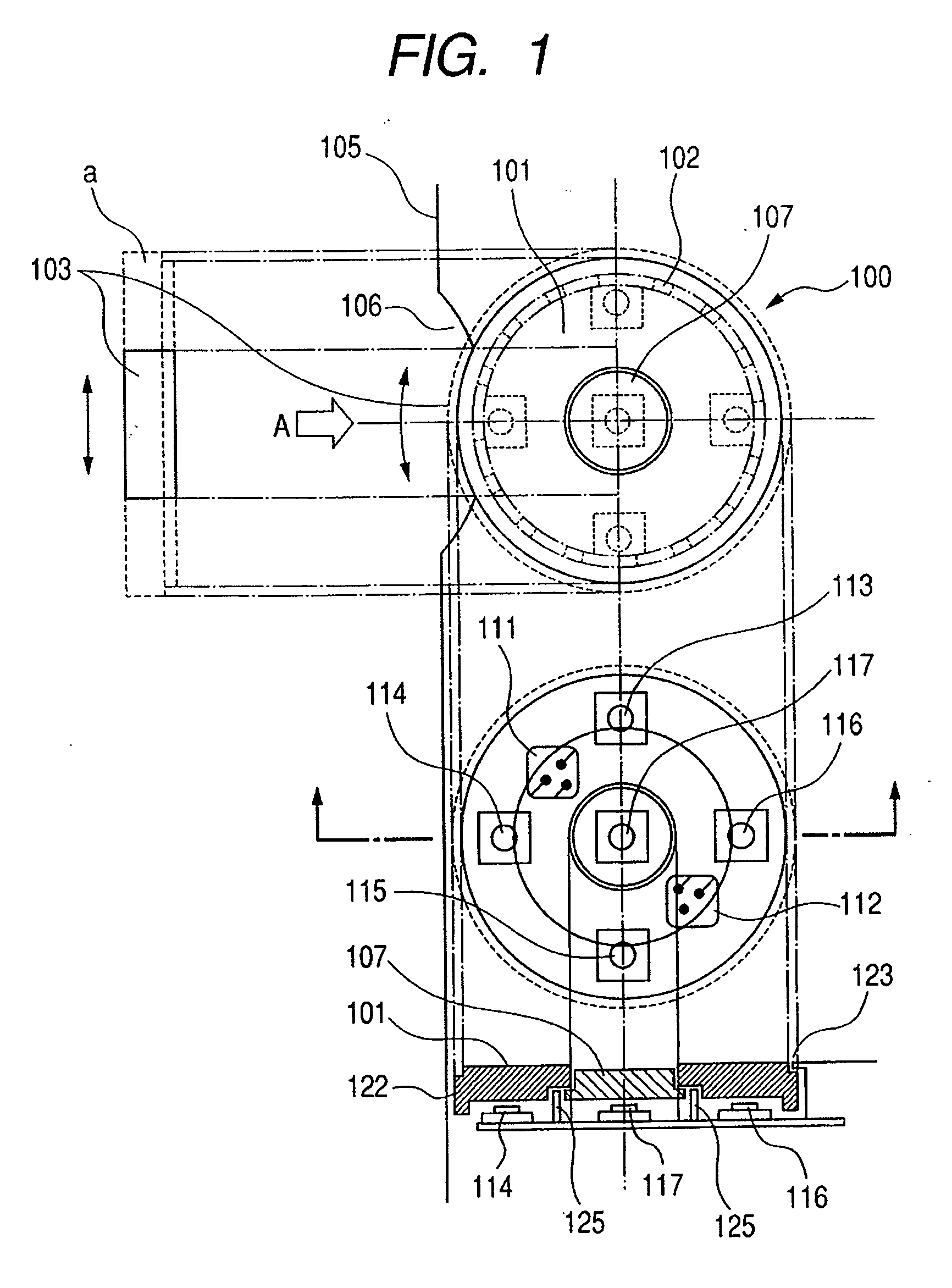
[0029]FIG. 1 is a diagram schematically showing a configuration of a multi-function input switch according to the embodiment of the present invention.

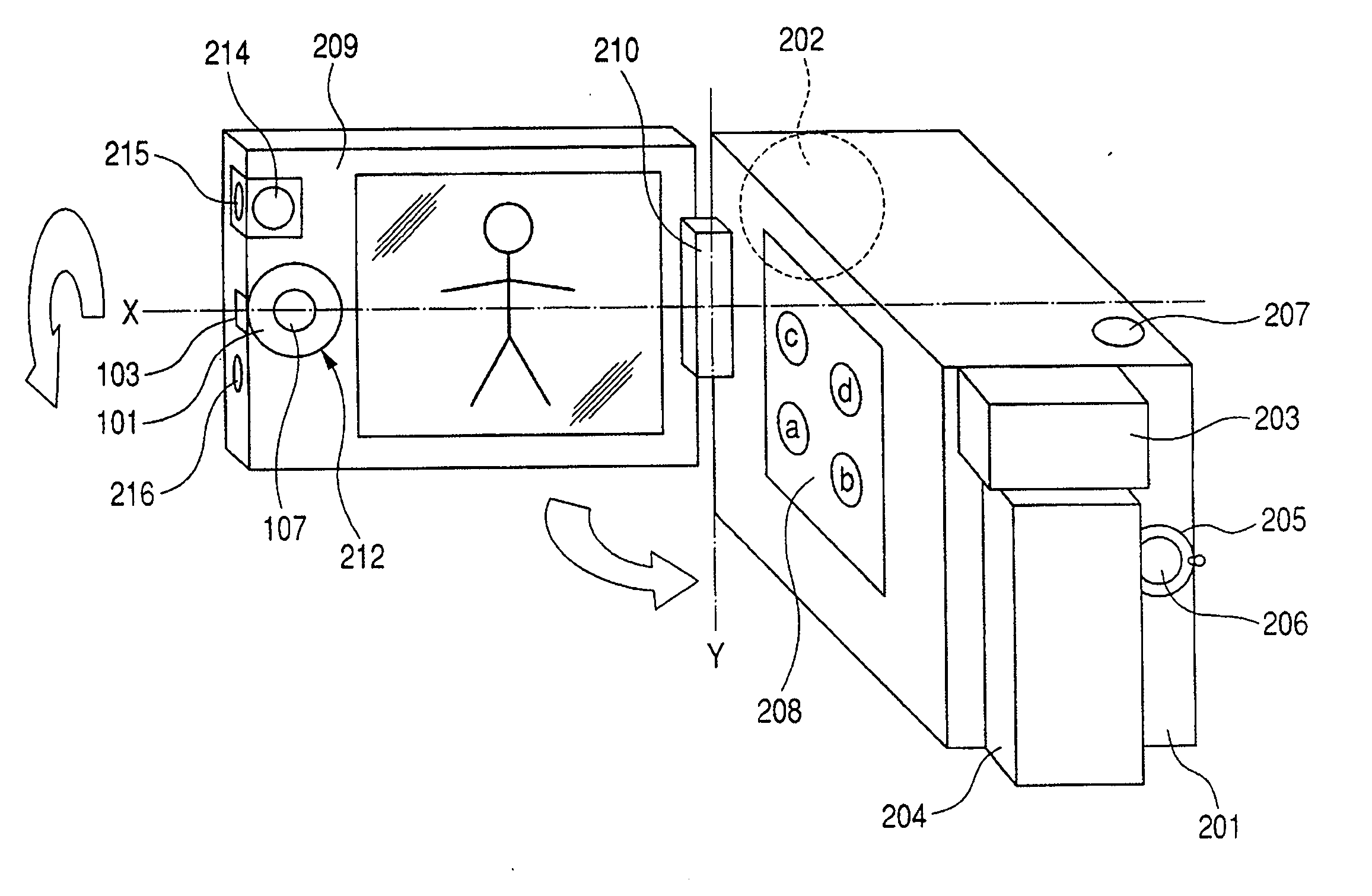
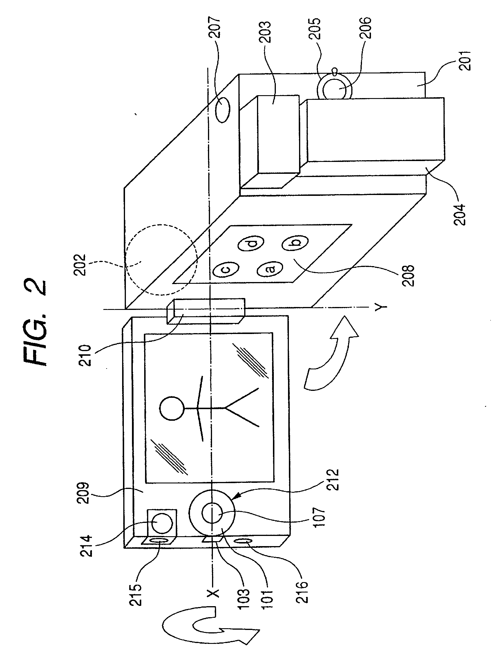
[0030] In FIG. 1, a multi-function input switch 100 is constituted by a ring-shaped-disc-like rotary dial 101 accommodated in an accommodation portion positioned at a side edge of a body frame 105. In the rotary dial 101, a ring-shaped plane is entirely exposed, and a part of a circumferential surface 103 indicated by the arrow A is exposed at a notch 106 of the body frame 105. A portion indicated by “a” of FIG. 1, of the circumferential surface 103 of the rotary dial 101 is placed behind the body frame 105, and thus cannot be seen from the direction of the arrow A.

[0031] The multi-function input switch 100 has a center switch 107 provided at the center of the rotary dial 101, tactile switches 113 to 116 provided ...


PUM


Abstract

A multi-function input switch comprises a rotary dial, and a joint portion connected to a side edge portion of a body frame including a display panel, wherein the rotary dial is arranged so that each of a circumferential surface portion and a circular plane portion is exposed from the body frame.

Description

BACKGROUND OF THE INVENTION [0001] 1. Field of the Invention [0002] The present invention relates to a multi-function input switch provided with a rotary dial. [0003] 2. Related Background Art [0004] There has been known a multi-function input switch such as a rotary encoder with a push switch mechanism (see Japanese Patent Application Laid-open No. 2001-052389). An operator uses the switch to select a character or a mode by rotating a rotary dial having a rotary encoding function and to determine the selected content by pressing the rotary dial from the peripheral portion thereof toward a direction perpendicular to a rotation axis. Multi-function input switches having determination mechanisms different from that described above include a mechanism in which the switch is depressed for determination by inclining a circular plane portion about an axis perpendicular to the rotation axis. [0005] In addition, there are switches where the rotary dial and the determination switch are separ...

Claims


Application Information

Patent Timeline
IPC IPC(8): H04N5/222
CPCH04N5/2251H04N5/23293H04N5/23216H04N23/531H04N23/62H04N23/631
Inventor MIURA, HIROYA
Owner CANON KK
Why Eureka
Try Eureka