System and method for biomass fractioning

a biomass and system technology, applied in the field of clean energy, can solve the problems of affecting affecting the efficiency of biomass fractionators, so as to facilitate the input of biomass and improve the yield of biomass fractionators

Active Publication Date: 2010-07-22
COOL PLANET ENERGY SYST
View PDF7 Cites 100 Cited by
  • Summary
  • Abstract
  • Description
  • Claims
  • Application Information

AI Technical Summary

Benefits of technology

[0010]In yet other embodiments of the invention, modular mechanical constructs are used to facilitate multiple fractionating stations, all within a pressure vessel, which can operate below atmospheric pressure, in open air, and at elevated pressures up to and including temperatures and pressures required for supercritical water as a working medium. Such embodiments incorporate multiple stage input and output airlocks to facilitate inputting biomass in bulk and discharging biochar and various fractionation streams from a potentially very high temperature and pressure internal environment, on an efficient basis. Some embodiments further accommodate variable thermal isolation and gas flow isolation between the various modular pyrolysis processing stations described herein. This allows for improved fractionator yield by way of substantial changes in temperature, pressure and local gas composition at various processing stations.

Problems solved by technology

In the early 21st century, global warming and its interrelationship with the widespread use of fossil fuels has become one of the major technological challenges.
At the low extreme, simple everyday cooking typically drives off water and starts to de-hydrolyze the biomass, causing the darkening and carmelization that we all associate with cooked foods.
Although some pyrolyzers are focused simply on producing syngas, there is considerable effort in the development of milder pyrolyzing conditions, which typically results in a condensed liquid commonly called bio-oil.
The fundamental problem with the resultant pyrolysis oil is that it is made up of hundreds to thousands of compounds, which are the result of subjecting the raw biomass to a wide range of temperature, time, and pressure profiles in bulk.
When this process is complicated by the thousands of major bio-compounds in the original bio-feedstock, the result is a nearly intractable array of resultant compounds all mixed together.
Pyrolysis oils from such processes are typically not thermodynamically stable.
Also, attempts to re-gasify pyrolysis oil typically result in additional chemical reactions, which produce additional biochar and a shift to lower molecular weight components in the resulting gas stream.
Although fairly high yields of pyrolysis oil can be achieved in laboratory scale experiments, larger industrial scale demonstration projects typically produce much lower yield.

Method used


Image

  • System and method for biomass fractioning
  • System and method for biomass fractioning
  • System and method for biomass fractioning

Examples


Embodiment Construction

[0020]The following diagrams and description present examples of the invention, but in no way, limit the application of the above concepts. The following designs are simply illustrative of their application.

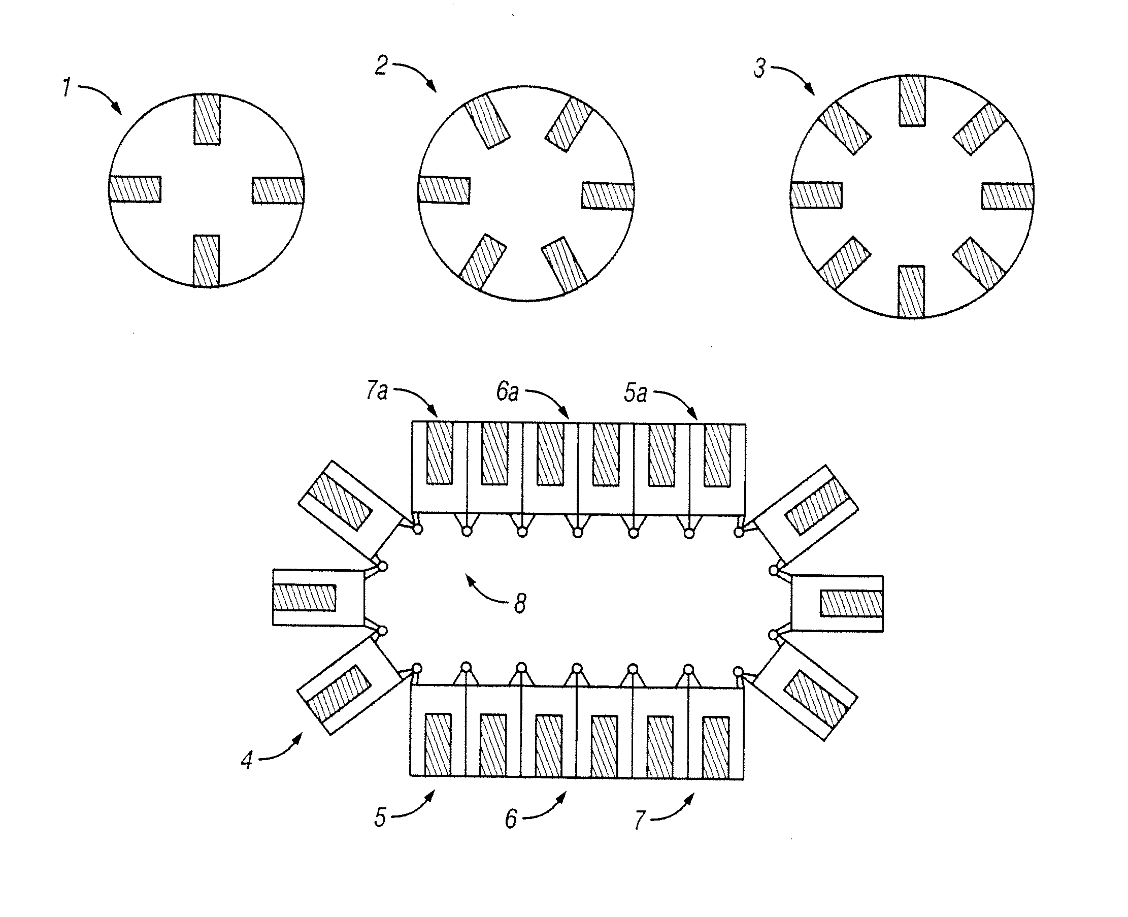
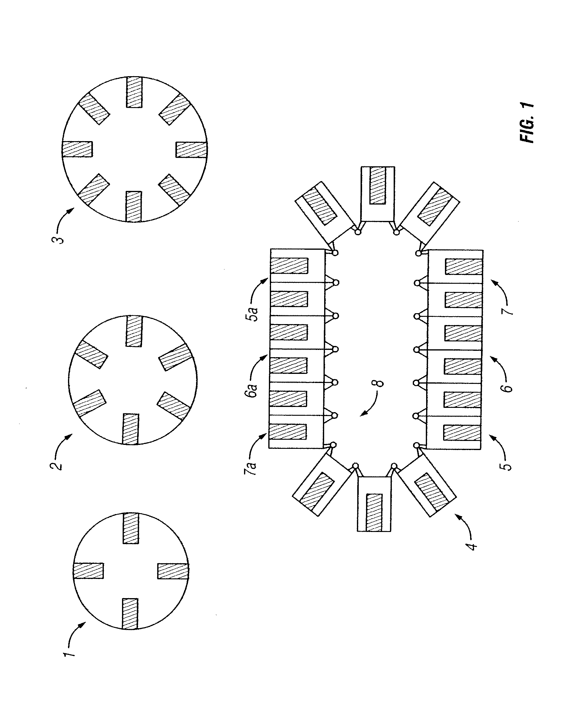
[0021]FIG. 1 is a diagram of example biomass reaction compartments in accordance with some embodiments of the invention. As illustrated in FIG. 1, biomass reaction compartments can be machined or cast into solid discs (1, 2, 3). These discs may rotate via any of a number of common drive mechanisms such as gear drives, chain drives, ratcheting sprockets, etc. The disc can rotate continuously. However, to simplify operation of individual processing stations, it may be desirable to step the disc, typically with the same number of indexes per rotation as there are biomass chambers. Although embodiments of the invention can have one or more chambers in a disc, preferably there are 4 to N chambers in a disc.

[0022]Still referring to FIG. 1, the biomass chamber is much wider and longer t...


PUM


Abstract

A biomass fractionator and method are described for inputting ground biomass and outputting several vapor streams of bio-intermediate compounds along with syngas and biochar. In one embodiment, a method for biomass fractioning, comprises dispensing biomass into thin sheets of ground biomass; subjecting the thin sheets to ramps of temperature; and selectively collecting various groups of compounds as they are released from the thin sheets.

Description

CROSS-REFERENCE TO RELATED APPLICATIONS[0001]This application claims priority from U.S. Provisional Patent Application Ser. Nos. 61 / 146,079, filed Jan. 21, 2009, the content of which is incorporated herein by reference in its entirety.FIELD OF THE INVENTION[0002]The present invention is directed towards clean energy, and more particularly, some embodiments of the invention provide systems and methods for biomass fractioning.DESCRIPTION OF THE RELATED ART[0003]In the early 21st century, global warming and its interrelationship with the widespread use of fossil fuels has become one of the major technological challenges. Finding ways to more effectively use renewable biomass is a very important avenue for addressing these issues. Prior to the beginning of the industrial revolution, wood and plant oils were the primary source of energy for pre-industrial civilizations, which used this energy mainly for heating, cooking, and light. During this early period, biomass was simply burned in o...

Claims


Application Information

Patent Timeline
Patent Type & Authority Applications(United States)
IPC IPC(8): F23J15/00
CPCC10B47/02C10B53/02C10B57/02C10C5/00C10B47/46F26B25/002F26B2200/02Y02E50/14Y02E50/32F26B3/18Y02E50/10Y02E50/30
Inventor CHEIKY, MICHAEL C.
Owner COOL PLANET ENERGY SYST
Why Eureka
Try Eureka