
Adjustable Bed With Massage Motor

a technology of adjustable beds and motors, applied in the field of adjustable beds, can solve the problems of less than desired net vibration applied to users lying on the mattress, and achieve the effect of improving massage capability and increasing the satisfaction of users with the bed

Inactive Publication Date: 2006-10-19
L & P PROPERTY MANAGEMENT CO
View PDF11 Cites 27 Cited by
  • Summary
  • Abstract
  • Description
  • Claims
  • Application Information

AI Technical Summary

Benefits of technology

[0008] The present invention provides an adjustable bed having an improved massage capability, thereby increasing the satisfaction of the user with the bed. The adjustable bed of the present invention is especially useful when multiple massage motors are incorporated into the bed.
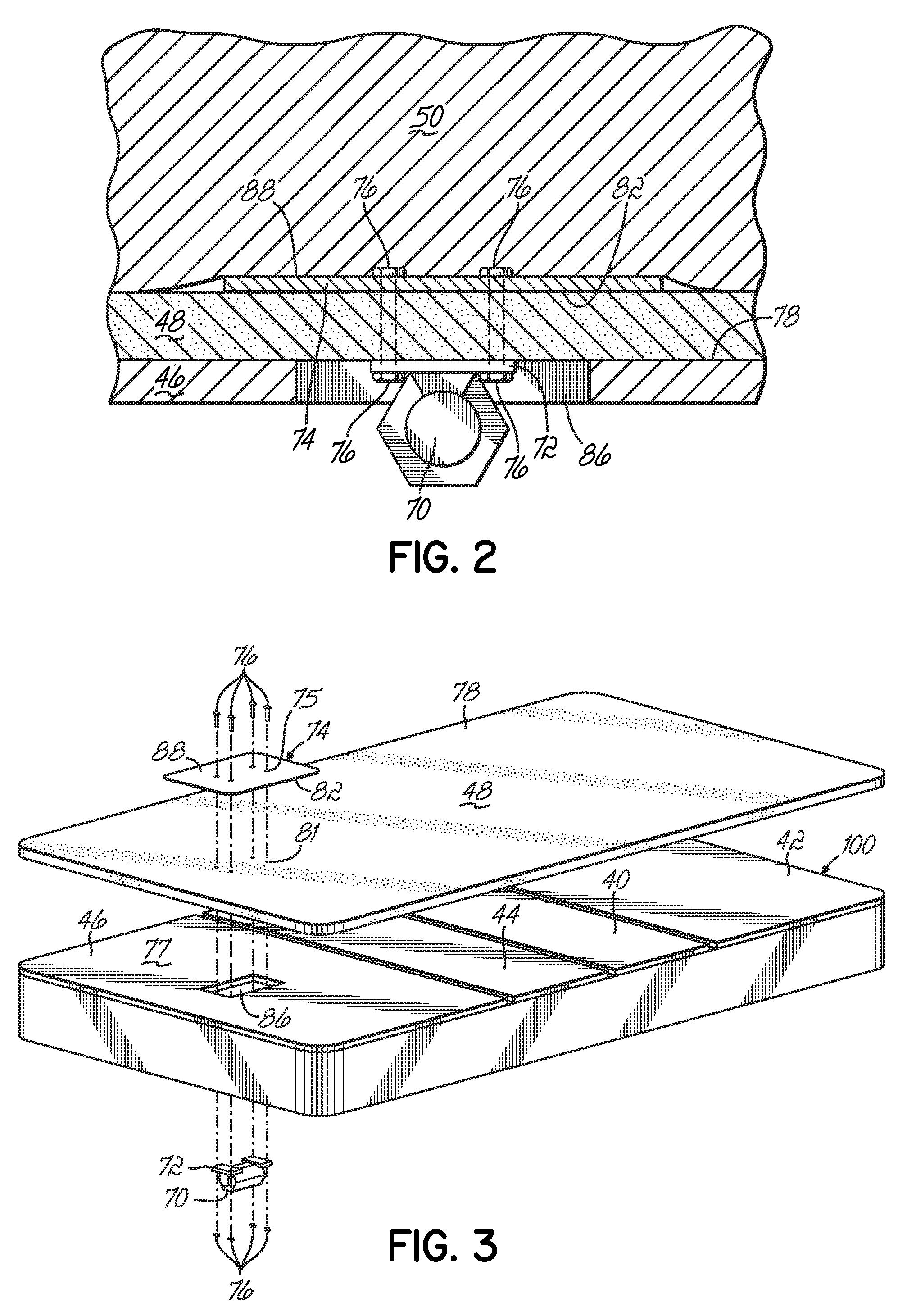
[0009] According to the principles of the present invention and in accordance with one embodiment, the adjustable bed of the present invention has a bed frame and a support section supported by the bed frame and adapted to support a mattress and a user laying on such mattress. The bed further has a mounting plate located on an upper surface of a mattress pad or base, and a massage motor mounted to and suspended by the mounting plate. This massage motor mounting structure greatly improves the transmission of vibrations created by the massage motor to a user laying on a mattress resting on the mattress pad or base.
[0010] In accordance with one aspect of the invention, the adjustable bed has a mattress base or pad having a thickness of approximately one inch for covering the support section. The mattress base may be made of any suitable material but is usually made of foam or fiber. In accordance with another aspect of the invention, the mounting plate is supported by the mattress base on the upper surface thereof; and the massage motor is suspended therefrom. Thus, the mounting plate is mounted such that vibrations from the massage motor are transmitted directly to the mounting plate and on to the mattress. The mounting mechanism reduces or eliminates any transfer of vibration to the adjustable bed frame or support platform.
[0011] In accordance with another aspect of the invention, the mounting plate may have at least one opening therein. Consequently, such mounting plate is made of less material and therefore less expensive to manufacture than a solid mounting plate.
[0012] In accordance with another aspect of the invention, the mounting plate may have rounded corners instead of square corners as in a rectangular mounting plate. Such a mounting plate is less likely to rub again or abrade the material surrounding the mattress core, a material known in the industry as upholstery.
[0013] In accordance with another aspect of the invention, the mounting plate may have reinforcing ribs between openings therein. Although such a mounting plate may be still flexible, it provides desirable rigidity for effectively and quietly transferring vibration from the massage motor to the mattress.

Problems solved by technology

The resulting or net vibration applied to a user lying on the mattress is often substantially less than is desired.

Method used


Image

  • Adjustable Bed With Massage Motor
  • Adjustable Bed With Massage Motor
  • Adjustable Bed With Massage Motor

Examples


Embodiment Construction

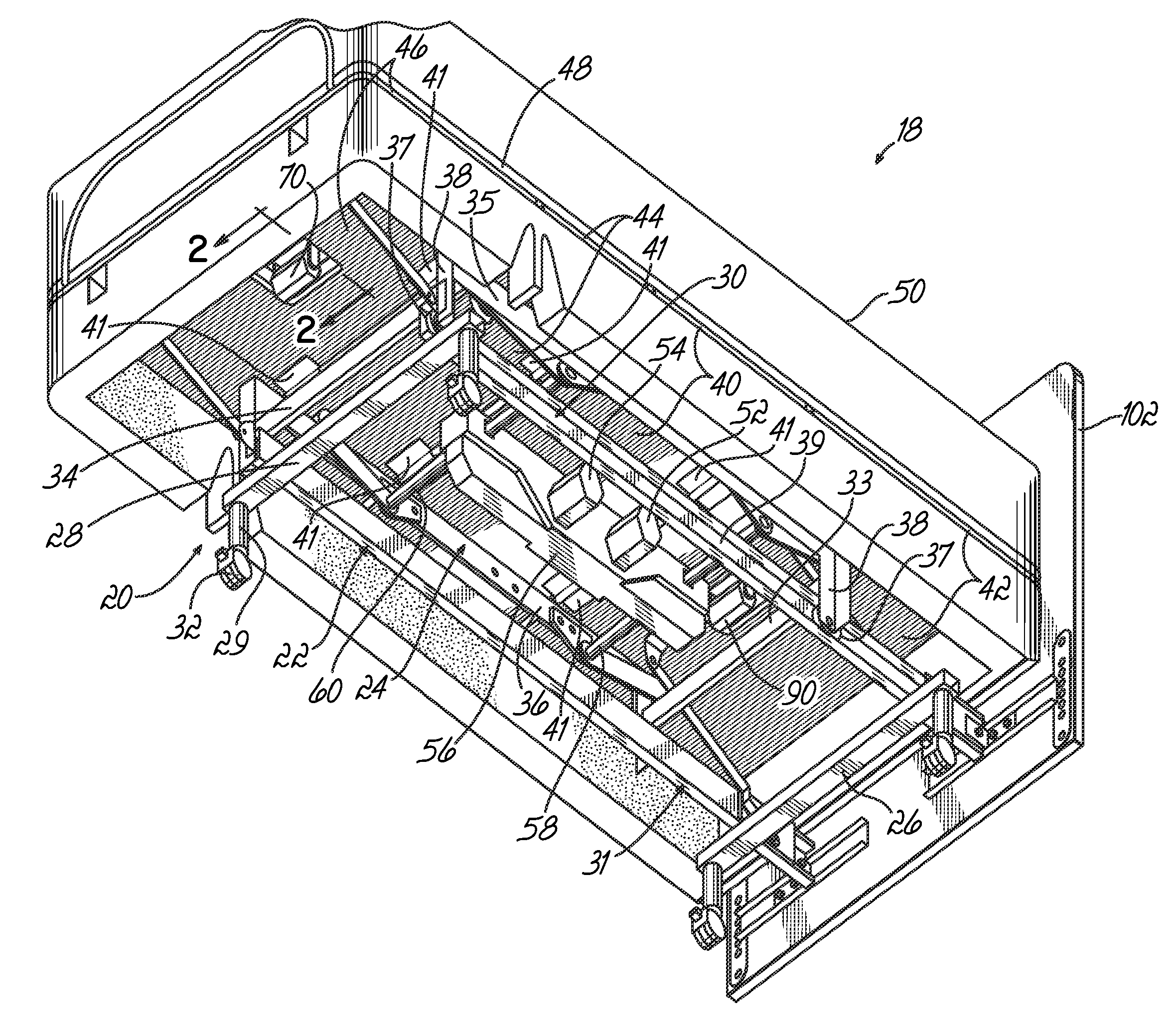
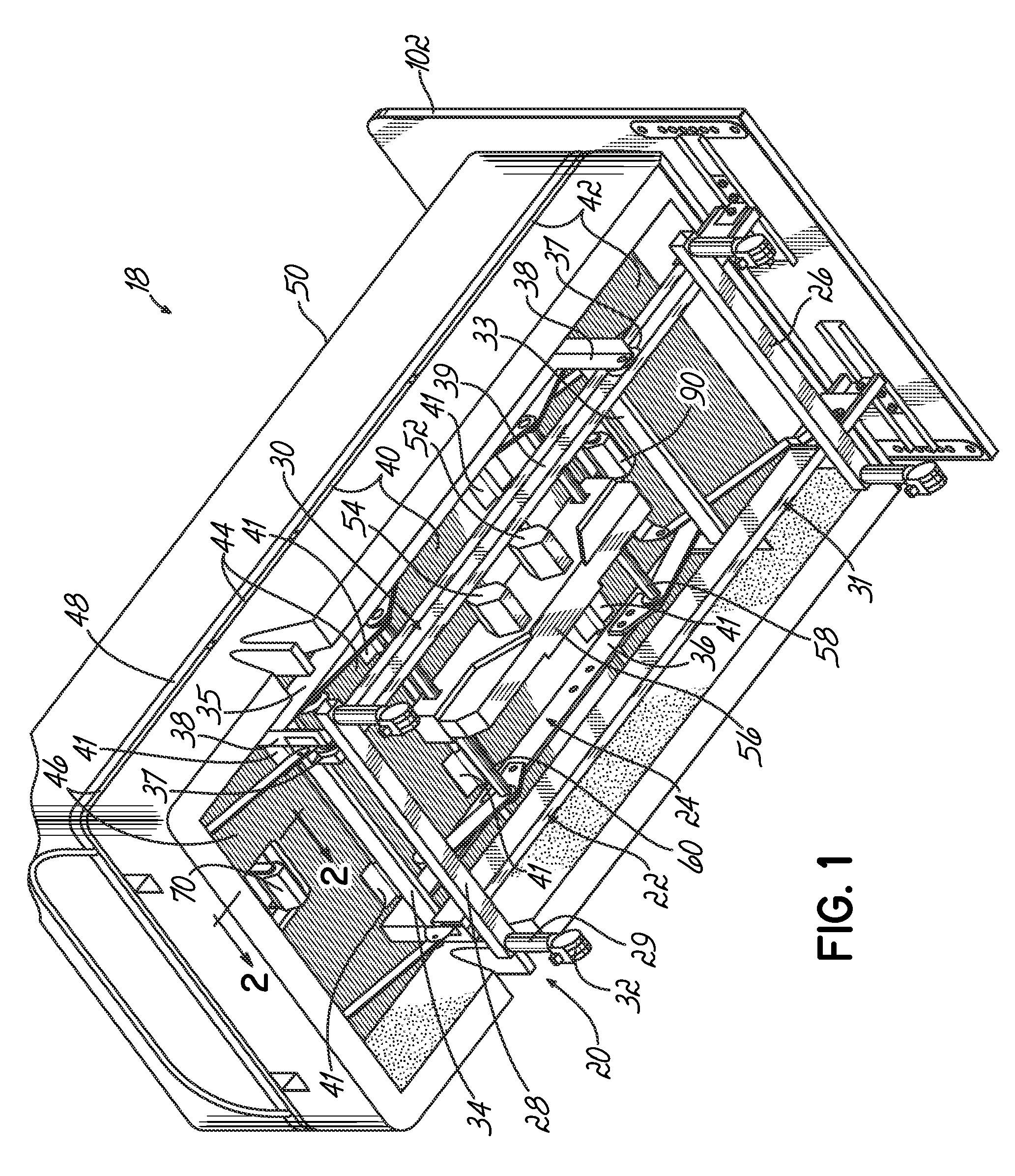
[0021] Referring to FIG. 1, an adjustable bed 18 includes a bed frame 20 comprised of a lower frame 22 and an upper frame 24 movably mounted on the lower frame 22. The lower frame 22 has head and foot end rails 26, 28 respectively, and left and right side rails 30, 31, respectively. The rails 26-31 are joined at their ends to form a generally rectangular lower frame 22. The lower frame 22 at the head end is joined to a head board 102. See FIG. 1. A plurality of caster brackets 29 are secured to and extend down from the end rails 26, 28 of the lower frame 22. A plurality of casters 32, each having a stem (not shown) are received inside the caster brackets 29 for supporting the adjustable bed 18 on the floor and enabling the adjustable bed 18 to be rolled from location to location.

[0022] The upper frame 24 includes a head rail 33, a foot rail 34 and left and right side rails 35, 36, respectively. The rails 33-36 are rigidly connected at their ends with fasteners to form the generally...


PUM


Abstract

An adjustable bed having an upper frame mounted to translate with respect to a lower frame. A center support is connected to the upper frame and has a head support pivotally connected to one end thereof. A thigh support is pivotally connected to the other end of the center support and a foot support is connected to the other end of the thigh support. The bed includes an improved mounting for a massage motor in which a massage motor is suspended from a mounting plate having openings therein resting on a mattress pad or base supported by an articulated support platform.

Description

CROSS REFERENCE TO RELATED APPLICATIONS [0001] This application is a continuation-in-part of U.S. patent application Ser. No. 11 / 108,995, filed Apr. 19, 2005 entitled “Adjustable Bed”, which is fully incorporated by reference herein.FIELD OF THE INVENTION [0002] This invention relates generally to adjustable beds and more particularly, to improvements to adjustable beds. BACKGROUND OF THE INVENTION [0003] Adjustable beds have been used for many years to permit the user to adjust the head and foot sections of the bed to different positions. While originally only manually adjustable, more recently, the head and foot sections are moved by motors operated by the user via a remote control. [0004] Adjustable beds were originally designed principally for use in medical environments by patients who had to spend long periods of time in bed for reasons of health, injury, etc. However, more recently, adjustable beds are also being used in residential environments by users who have no health or...

Claims


Application Information

Patent Timeline
Patent Type & Authority Applications(United States)
IPC IPC(8): A47D9/02
CPCA47C21/006A61H23/02Y10S5/933A61H2203/0443A61H2201/0142
Inventor LONG, THOMAS P.
Owner L & P PROPERTY MANAGEMENT CO
Learn More