Cap for wiper connector

Inactive Publication Date: 2006-10-19
KB WIPER SYST CO LTD +1
View PDF6 Cites 42 Cited by
  • Summary
  • Abstract
  • Description
  • Claims
  • Application Information

AI Technical Summary

Benefits of technology

[0008] The object of the present invention is to provide a cap accommodating the portion where a wiper connector is provided and having a spoiler thereof

Problems solved by technology

The rising of the wiper blade hinders the wiping operation.
Thus, the appearance is not so aesthetic because of the discontinuity of the spoiler caused by provision of the wiper connector 30.
Furth

Method used


Image

  • Cap for wiper connector
  • Cap for wiper connector
  • Cap for wiper connector

Examples


Example

[0026] Hereinafter, the present invention will be described in detail with reference to accompanying drawings. The invention will now be described based on the preferred embodiments, which do not intend to limit the scope of the present invention, but exemplify the invention. All of the features and the combinations thereof described in the embodiments are not necessarily essential to the invention.

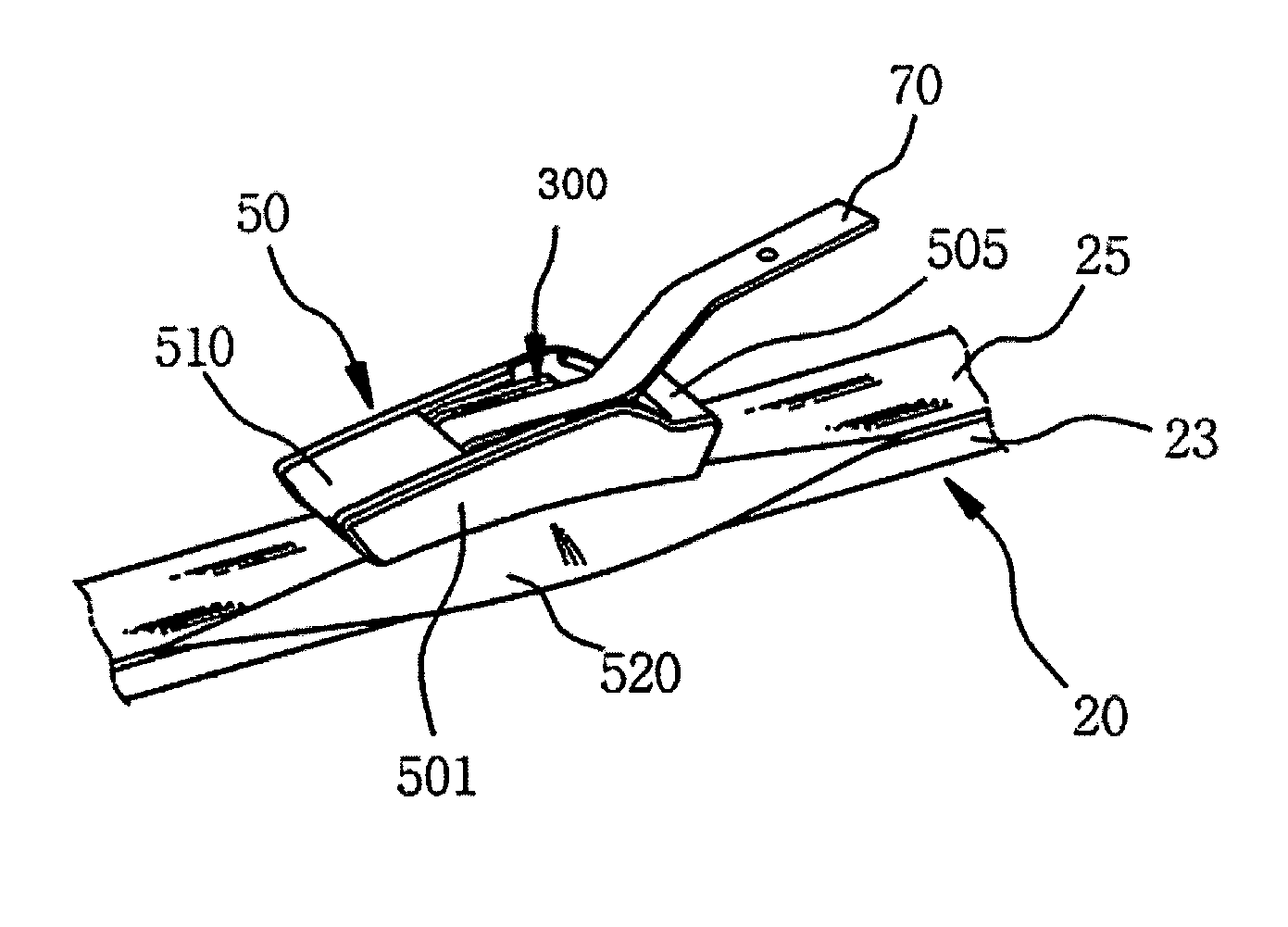
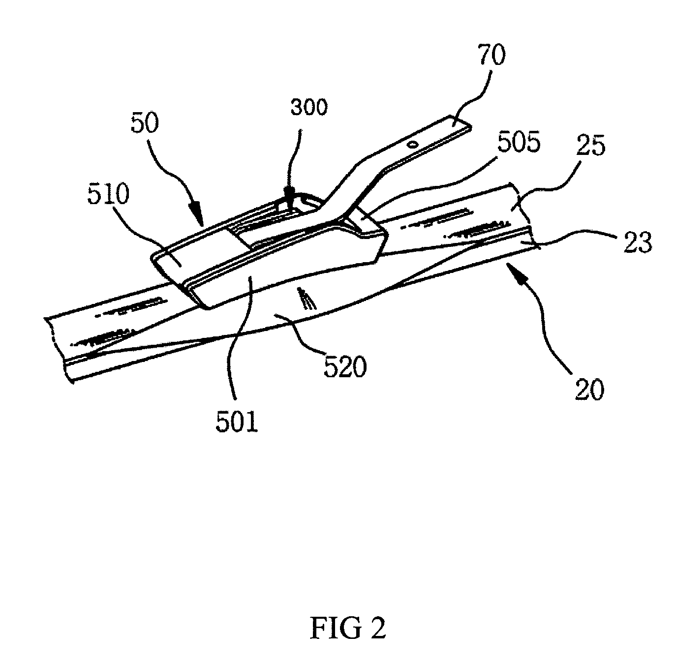
[0027]FIG. 2 shows a perspective view of a wiper to which a cap for wiper connector according to the present invention is connected. The wiper connector and the cap for wiper connector will be described hereinafter with reference to FIG. 2.

[0028] As shown in FIG. 2, the cap 50 for wiper connector is releasably fastened to a wiper connector 300 that is provided at about longitudinally center of elastic support member 25 supporting flexible strip which is directly contacting with a windshield. A wiper arm 70 is connected to the connecting member 40 of the wiper connector 300.

[0029] The w...


PUM


Abstract

The present invention relates to a cap for a wiper connector of a motor vehicle. A cap for wiper is comprised of a pair of side walls facing each other to form space where at least a portion of the wiper connector is accommodated, a connecting part for connecting the pair of side walls, a mounting part which is releasably mounted to the wiper connector and a flab protruding outwardly from at least one of the the side walls.

Description

[0001] This patent application claims priority from Korean Patent Application No. 10-2005-0031952 filed on Apr. 18, 2005, the contents of which are incorporated herein by reference. FIELD OF THE INVENTION [0002] The present invention relates to a cap for a wiper connector of a motor vehicle. More particularly, but not exclusively the present invention relates to a cap for a wiper connector provided to accommodate wiper connector of a flat type wiper blade assembly. BACKGROUND OF INVENTION [0003] A wiper blade assembly is provided in a windshield of a vehicle to wipe out drops of the rain on the windshield so that driver can secure his / her view. The wiper blade assembly is driven by a wiper arm which is operated by an operating motor. A wiper connector is provided in order to connect the wiper arm with the wiper blade assembly. Generally, the wiper blade assembly is provided with a guide clip to which a wiper connector is fastened. The wiper arm is connected to the wiper connector af...

Claims


Application Information

Patent Timeline
IPC IPC(8): B60S1/40
CPCB60S1/3867B60S2001/4035B60S2001/3843B60S1/40F24F5/0042
Inventor SON, IL HO
Owner KB WIPER SYST CO LTD
Why Eureka
Try Eureka