
Variable air induction apparatus

a variable air induction and air intake technology, which is applied in the direction of combustion engines, combustion air/fuel air treatment, charge feed systems, etc., can solve the problems of reducing air intake efficiency, increasing so as to improve air intake efficiency and increase the size of driving devices

Inactive Publication Date: 2006-10-26
DENSO CORP +1
View PDF1 Cites 9 Cited by
  • Summary
  • Abstract
  • Description
  • Claims
  • Application Information

AI Technical Summary

Benefits of technology

[0008] The present invention is achieved in view of the above-described issues, and has an object to provide a variable air induction apparatus that can improve an air intake efficiency without increasing a size of a driving device thereof.

Problems solved by technology

As a result, undesirable intake air pulsation occurs not only in the short air intake passage but also in the long air intake passage, to decrease an air intake efficiency.
This increases a size of the driving device and a size of the variable air induction apparatus.

Method used


Image

  • Variable air induction apparatus
  • Variable air induction apparatus
  • Variable air induction apparatus

Examples


first embodiment

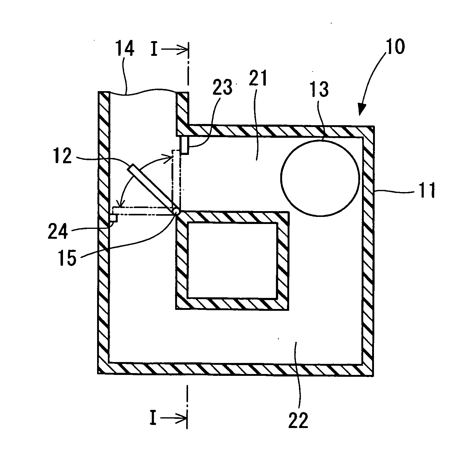
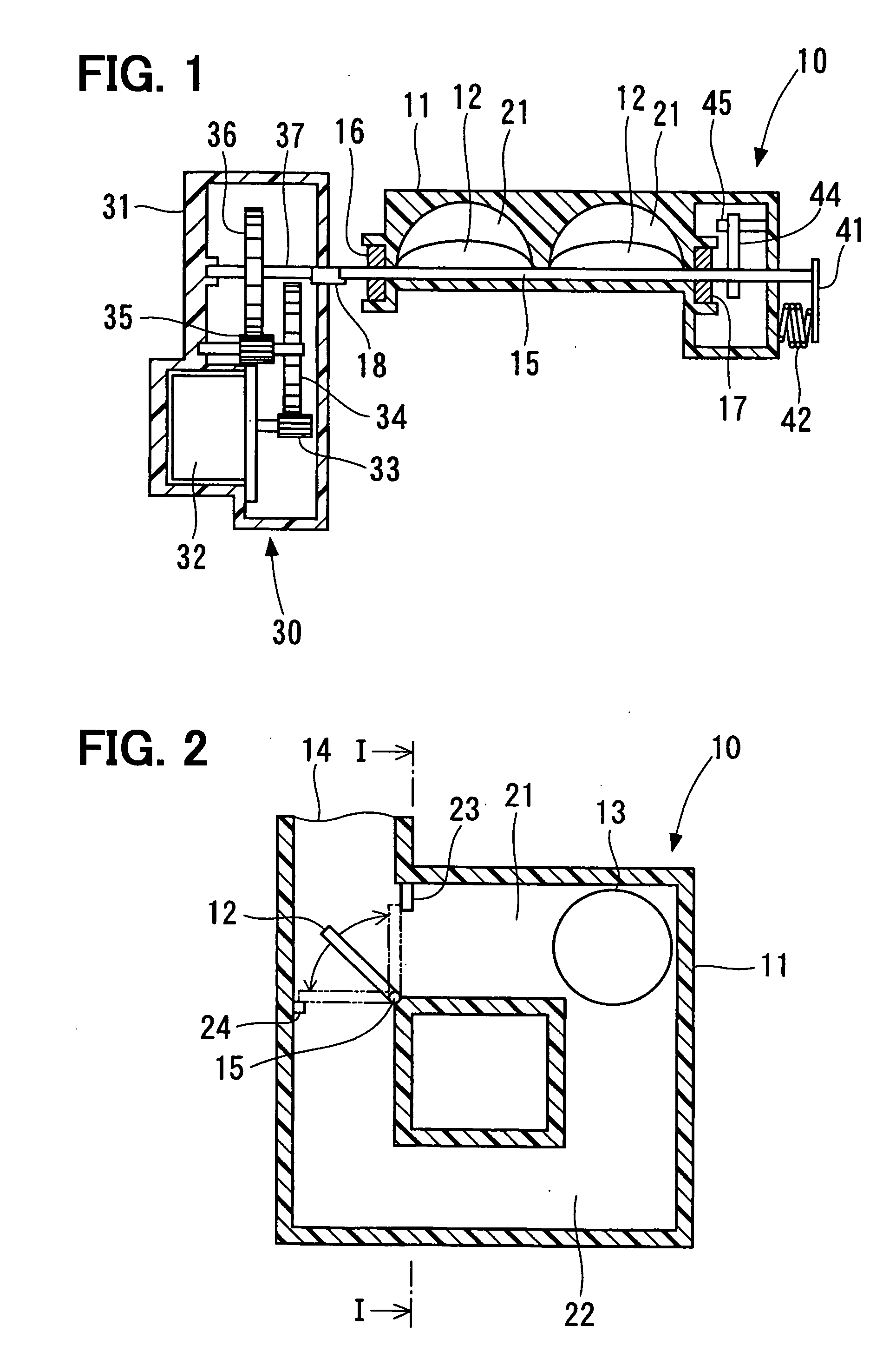
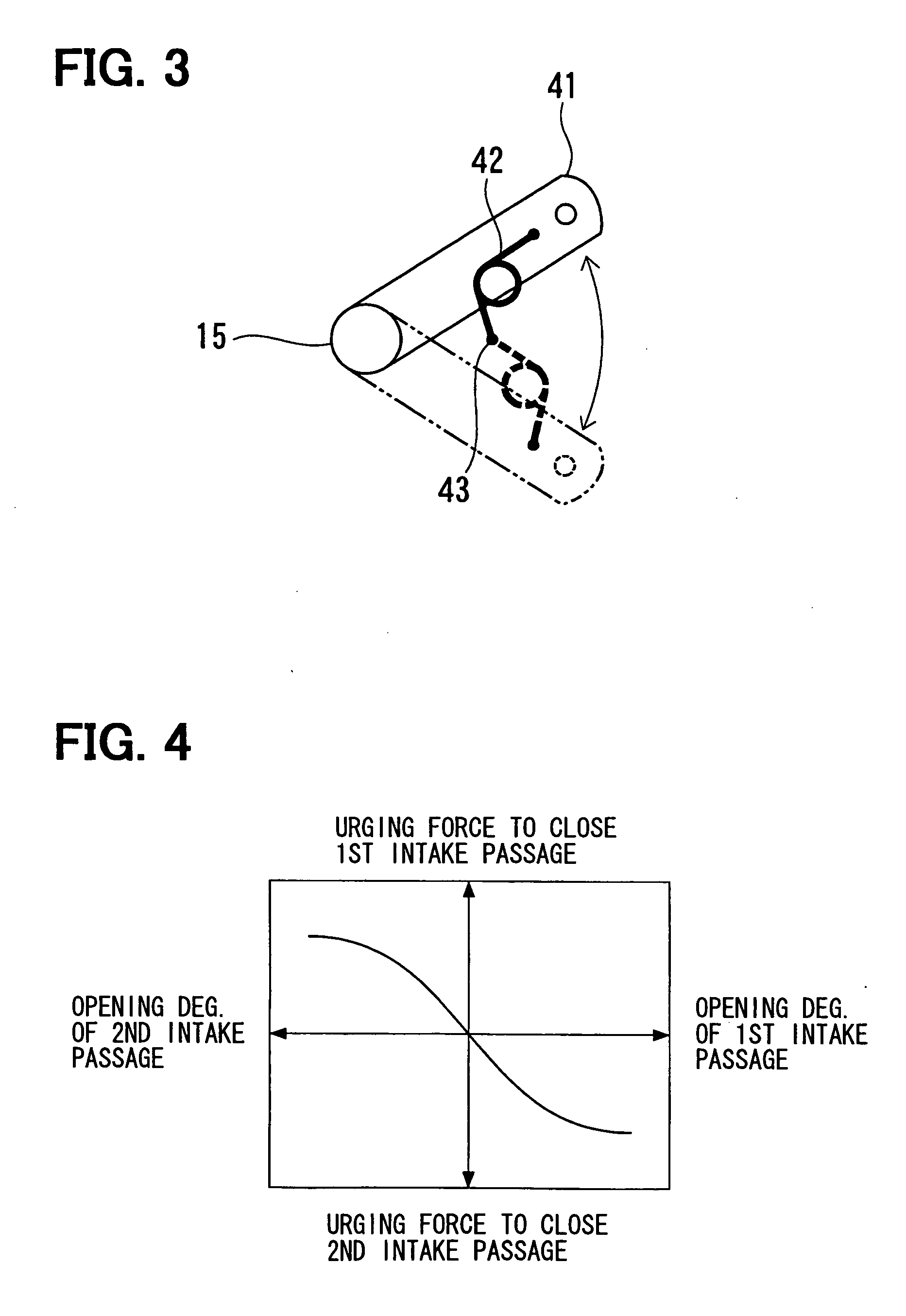
[0017] A variable air induction apparatus 10 according to a first embodiment of the present invention, which is shown in FIGS. 1 and 2, is installed at an air intake side of a gasoline engine. The variable air induction apparatus 10 is provided with a housing 11, which is formed from a resin, for example and a butterfly valves 12, which corresponds to the valve element according to the present invention. As shown in FIG. 2, the housing 11 forms first air intake passages 21 and second air intake passages 22, which respectively extend from an air inlet 13 to an air outlet 14. The first air intake passages 21 connect the air inlet 13 with the air outlet 14 in distances shorter than the second air intake passages 22 do. The second air intake passages 22 connect the air inlet 13 with the air outlet to detour the first air intake passages 21. That is, an overall length of the first air intake passage 21 is shorter than that of the second air intake passage 22. As shown in FIG. 1, a plural...

second embodiment

[0034]FIG. 5 depicts a variable air induction apparatus 10 according to a second embodiment of the present invention. Components substantially as same as those in the first embodiment are assigned the same referential numerals as in the first embodiment, and not especially described in the following.

[0035] As shown in FIG. 5, in the variable air induction apparatus 10 according to the second embodiment, the shaft 15 is urged not only by the spring 51, which corresponds to the urging device and the urging means according to the present invention, but also a supplemental spring 52, which corresponds to the supplemental urging device according to the present invention. As shown in FIG. 6, the spring 51 has urging force characteristics as same as that in the first embodiment. The supplemental spring 52 assists the urging force of the spring 51 exclusively to one side. Accordingly, as shown in FIG. 6, a resultant force of the urging force of the spring 51 and the urging force of the sup...


PUM


Abstract

In a variable air induction apparatus, a valve element is switched between one side to open a first air intake passage and close a second air intake passage, and the other side to open the second air intake passage and to close the first air intake passage. The first air intake passage and the second air intake passage have lengths different from each other. The valve element is fixed on a shaft member to rotate integrally with the shaft. A driving device applies a driving force to rotate the shaft member. An urging device urges the shaft member to rotate the valve element to be switched to any one of the one side and the other side.

Description

CROSS REFERENCE TO RELATED APPLICATION [0001] This application is based upon and claims the benefit of priority of Japanese Patent Application No. 2005-123427 filed on Apr. 21, 2005, the content of which is incorporated herein by reference. FIELD OF THE INVENTION [0002] The present invention relates to a variable air induction apparatus for an internal combustion engine, especially for switching between a long and a short air intake passages. BACKGROUND OF THE INVENTION [0003] Variable air induction apparatuses are conventionally used to improve a torque of an internal combustion engine by varying a length of an air intake passage in accordance with a number of revolutions of the internal combustion engine. In these variable air induction apparatus, the length of the air intake passage is increased when the number of revolutions of the internal combustion engine is relatively small, and the length of the air intake passage is decreased when the number of revolutions of the internal ...

Claims


Application Information

Patent Timeline
Patent Type & Authority Applications(United States)
IPC IPC(8): F02M35/10
CPCF02B27/02F02D9/103Y02T10/146F02D9/1095F02D11/10F02D9/1065F02B27/0294F02B27/0215F02B27/0273F02B27/0278Y02T10/12
Inventor KANDA, TSUYOSHIYAMADA, YOSHICHIKAMURATA, TAISUKEKAMEDA, YASUTOSHINAKAWATASE, AKIRA
Owner DENSO CORP
Learn More