Housing for axial flow heat-dissipating fan

a technology of axial flow and heat dissipation fan, which is applied in the direction of liquid fuel engines, machines/engines, combination engines, etc., can solve the problems of unstable connection between, inability to reliably connect two heat dissipating fans of this type, and inability to make stable contact, etc., to achieve the effect of improving the stability of assembly

Inactive Publication Date: 2005-12-22
SUNONWEALTH ELECTRIC MACHINE
View PDF3 Cites 9 Cited by
  • Summary
  • Abstract
  • Description
  • Claims
  • Application Information

AI Technical Summary

Benefits of technology

[0007] An object of the present invention is to provide a housing for an axial flow heat-dissipating fan with improved assembling stability.
[0008] Another object of the present invention is to provide a housing for an axial flow heat-dissipating fan with improved assembling flexibility.
[0010] Still another object of the present invention is to provide a housing for an axial flow heat-dissipating fan with lowered blowing noise. SUMMARY OF THE INVENTION
[0014] Two of the axially extending slits adjacent to each other may be communicated with each other, forming a slit with an enlarged end to increase air intake efficiency in an axial direction and to increase air intake efficiency in a radial direction. The enlarged end of the slit extends through an end face of the first end of the annular wall and is communicated with the air inlet.
[0015] In another embodiment of the invention, the annular wall further includes at least one engaging plate extending radially outward from the first end that defines the air inlet. Further, the annular wall further includes at least one engaging plate extending radially outward from the second end that defines the air outlet. The engaging plate includes at least one side that is coplanar with an associated assembling section. Each axially extending slit includes an outer end and an inner end narrower than the outer end, providing a pressurizing effect while drawing air through the axially extending slits.

Problems solved by technology

Airflow passing through the radial slits of one of the blowers interferes with airflow passing through the radial slits of another blower, causing turbulences.
Further, the spacers include portions projected outwardly from the wall, which protruded portions result in unstable contact and unstable connection between two adjacent planar peripheral sections respectively of two adjacent blowers.
However, reliable connection between two heat-dissipating fans of this type is impossible, as the axial guide blades of the heat-dissipating fan provide no structure for such connection.

Method used


Image

  • Housing for axial flow heat-dissipating fan
  • Housing for axial flow heat-dissipating fan
  • Housing for axial flow heat-dissipating fan

Examples


Embodiment Construction

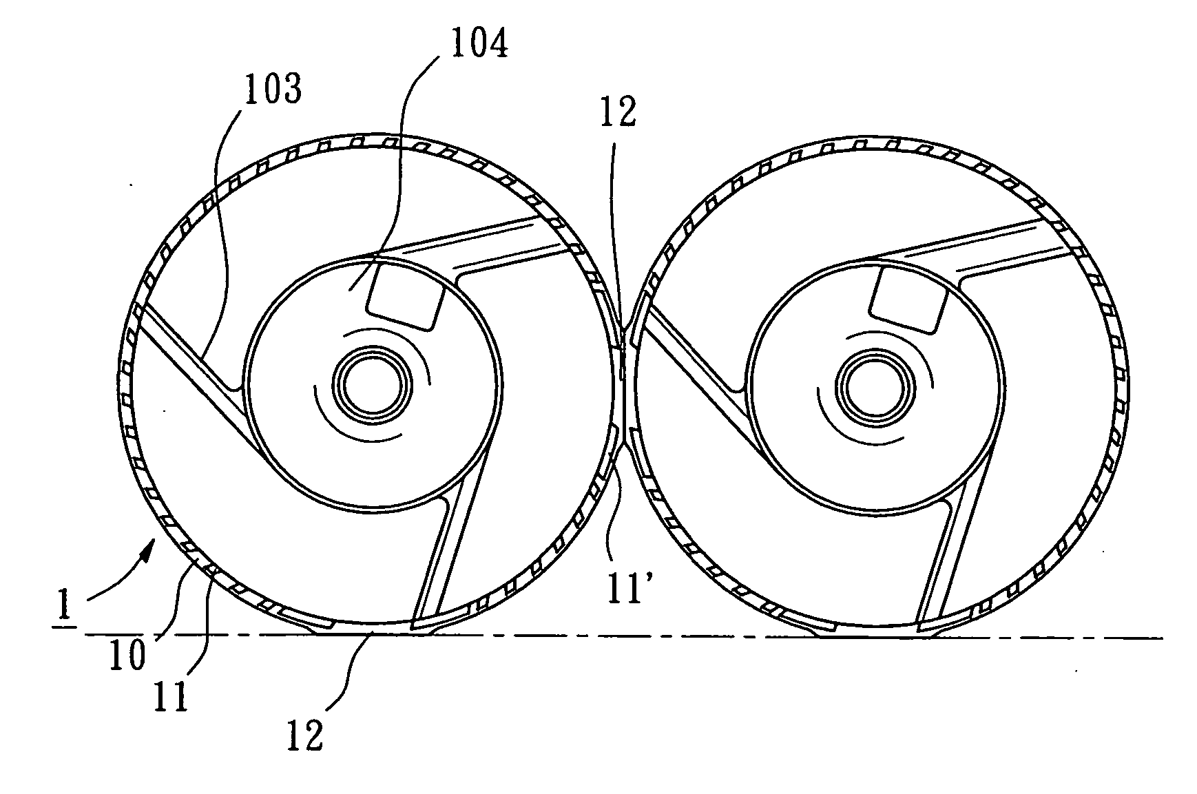
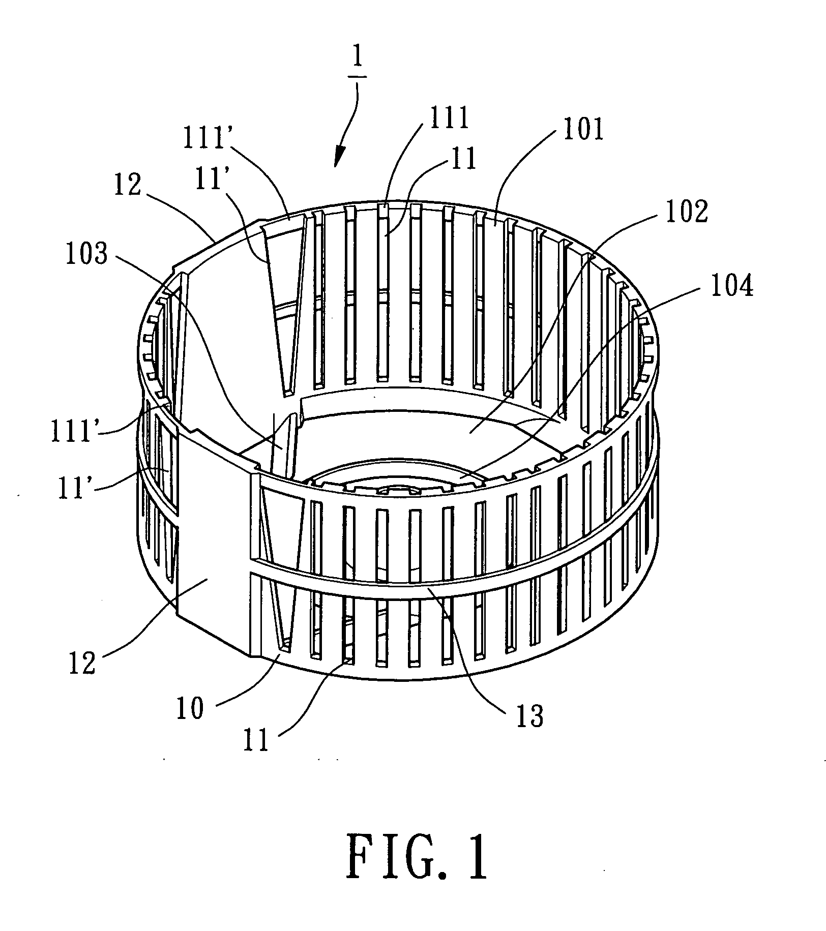
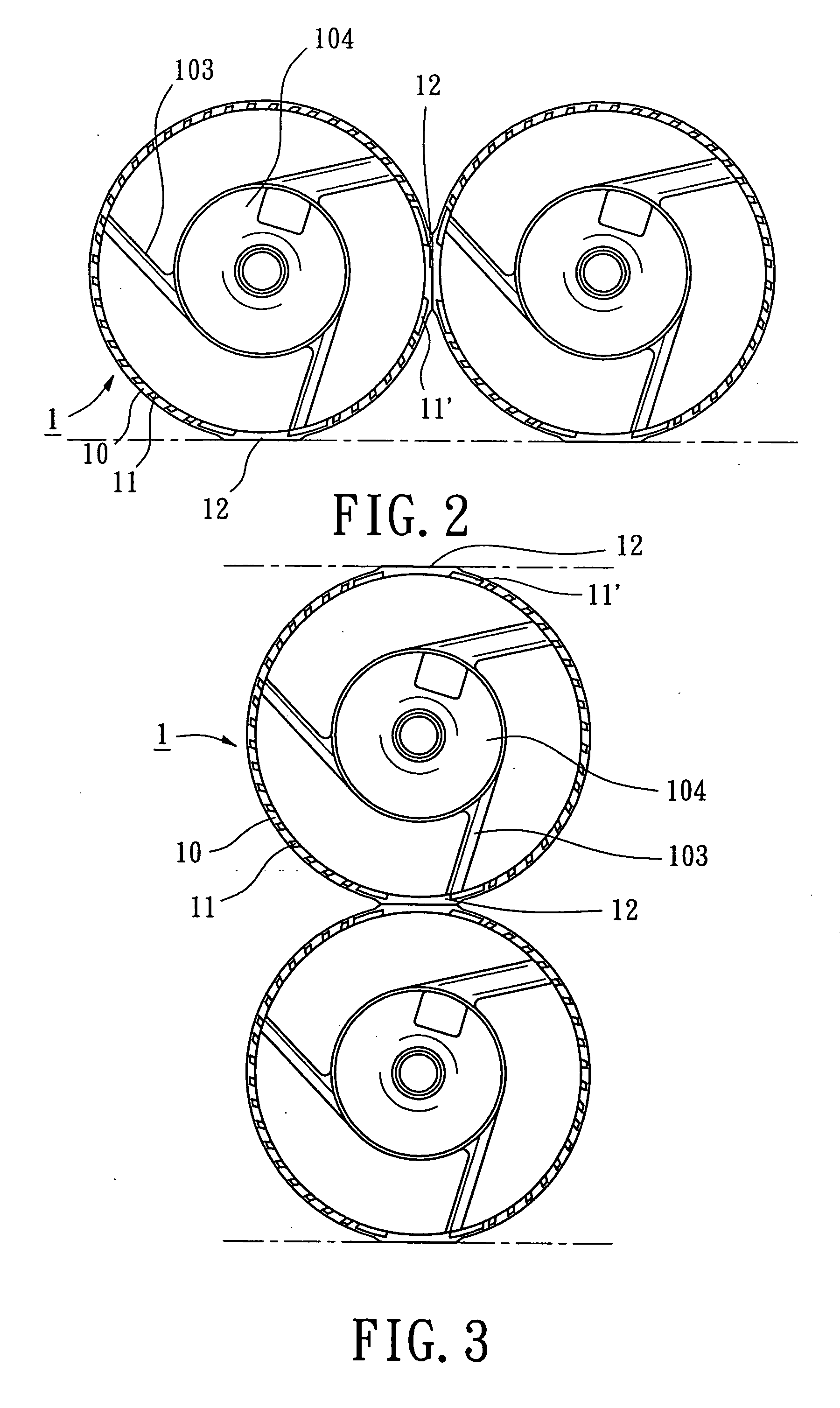
[0024]FIG. 1 is a perspective view of a first embodiment of a housing for an axial flow heat-dissipating fan in accordance with the present invention. FIG. 2 is a sectional view illustrating connection of two housings in FIG. 1.

[0025] The housing 1 for an axial flow heat-dissipating fan in accordance with the present invention comprises an annular wall 10 that is substantially circular when viewed in section. The annular wall 10 includes an air inlet 101 in an end thereof and an air outlet 102 in the other end thereof. A base 104 is mounted in the air outlet 102 and supported by a plurality of ribs 103 between the base 104 and the annular wall 10. The annular wall 10 further includes a plurality of axially extending slits 11 equispaced along a circumference of the annular wall 10 for drawing ambient air surrounding the annular wall 10. Each axially extending slit 11 includes an end 111 extending through an end face of the annular wall 10 and communicated with the air inlet 101. In ...


PUM


Abstract

A housing for an axial flow heat-dissipating fan includes an annular wall including an air inlet in a first end thereof and an air outlet in a second end thereof. A motor of an axial flow heat-dissipating fan is received in the annular wall. A plurality of axially extending slits are defined in a circumference of the annular wall. At least two assembling sections are formed on the circumference of the annular and spaced from each other. One of the at least two assembling sections of the housing is engaged with one of at least two assembling sections of a similarly constructed housing.

Description

BACKGROUND OF THE INVENTION [0001] 1. Field of the Invention [0002] The present invention relates to a housing for an axial flow heat-dissipating fan. In particular, the present invention relates to a housing for an axial flow heat-dissipating fan for increasing an inlet amount of air and for providing a reinforced structure. [0003] 2. Description of Related Art [0004] U.S. Pat. No. 6,132,171 discloses a blower that sucks air inside a wall through radial slits as a fan rotates. The wall is formed away from ends of fan blades. Outer peripheral sections of the wall are planar and substantially flush with a rectangular casing body at a middle of upper, lower, right, and left sides of the body. The radial slits are formed in the wall for increasing the air inlet amount. A plurality of annular plates are spaced from each other and stacked in a direction along an axis of rotation of the fan to form the wall with radial slits. Spacers forming and supporting the slits are arranged toward th...

Claims


Application Information

Patent Timeline
Patent Type & Authority Applications(United States)
IPC IPC(8): F04D13/04F04D29/52F04D29/54F04D29/66
CPCF04D29/526F04D29/667F04D29/545F04D25/0613
Inventor HORNG, ALEXFANG, MEI-CHIH
Owner SUNONWEALTH ELECTRIC MACHINE
Why Eureka
Try Eureka