
Electric junction box

A technology for electrical junction boxes and to boxes, which is applied in the direction of electrical components, multiple connection components, circuits or fluid pipelines, etc. It can solve the problems of increasing the number of components and assembly processes, improving the strength and ensuring the stability of assembly, and achieving Easy insertion, preventing instability effect

Inactive Publication Date: 2011-05-11
SUMITOMO WIRING SYST LTD
View PDF9 Cites 6 Cited by
  • Summary
  • Abstract
  • Description
  • Claims
  • Application Information

AI Technical Summary

Problems solved by technology

However, in the case of providing the holder, the number of components and assembly processes are increased
In addition, the peripheral wall that is in direct contact with the connector is kept unfolded, and then a gap may be formed between the peripheral wall and the holder depending on the dimensional accuracy of the peripheral wall and the holder, thereby causing limitations in improving strength and securing assembly stability

Method used


Image

  • Electric junction box
  • Electric junction box
  • Electric junction box

Examples


Embodiment Construction

[0030] The details of the invention are described below by way of examples and are intended only to be an illustrative discussion of the embodiments of the invention and to provide the most useful and understandable illustration of the principles and conceptual aspects of the invention. In this regard, it is not desirable to describe too much structural details that do not contribute to the basic understanding of the present invention. Those skilled in the art can clearly understand that the present invention is implemented in practice on the basis of the description and the accompanying drawings. in what form.

[0031] Embodiments of the present invention are explained below with reference to the drawings.

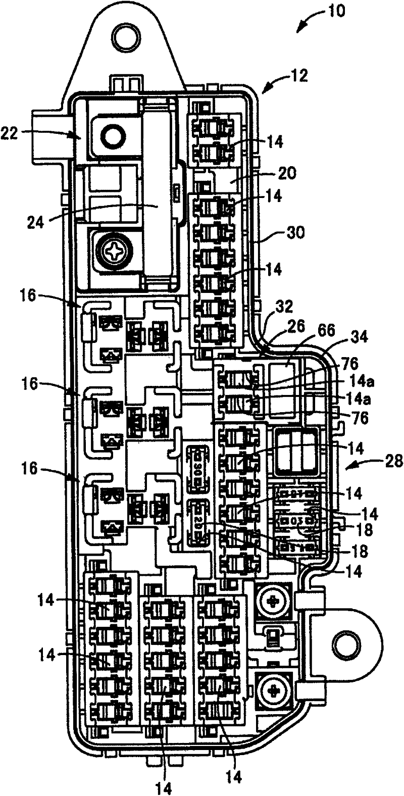
[0032] figure 1In FIG. 1 , an electrical junction box 10 as an embodiment of the present invention is first shown. The electrical junction box 10 according to the present invention can be mounted on any suitable vehicle such as a motorcycle, and has a longitudinal box m...


PUM


Abstract

Vertical bus bars are mounted on a first surface of a box main body. A connection terminal of the vertical bus bars projects inside a fitting peripheral wall of a connector fitting portion provided to a second surface of the box main body. A retainer is provided off of the electrical component connection portion, the retainer holding the vertical bus bars disengageably from the first surface.

Description

[0001] Pursuant to the provisions of Title 35, United States Code, Section 119, this application claims priority to Japanese Application No. 2009-254454, filed November 5, 2009, which is hereby incorporated in its entirety in its entirety. technical field [0002] The present invention relates to an electric junction box mounted to a vehicle or the like, and more particularly, the present invention relates to an electric junction box provided with an electronic component mounting portion and a bus bar for conduction with the electric component mounting portion. Background technique [0003] Electrical junction boxes such as relay boxes and fuse boxes are commonly used in vehicles and the like to improve the efficiency and maintenance of electric wires. Electrical components such as relays and fuses and conductive components such as bus bars are adapted to be mounted in the box main body of the electrical junction box. Electric power from the battery or the like is thereby su...

Claims


Application Information

Patent Timeline
Patent Type & Authority Applications(China)
IPC IPC(8): H02G3/08H02G3/16
CPCB60R16/0238H05K7/026
Inventor 松井俊幸
Owner SUMITOMO WIRING SYST LTD
Learn More