

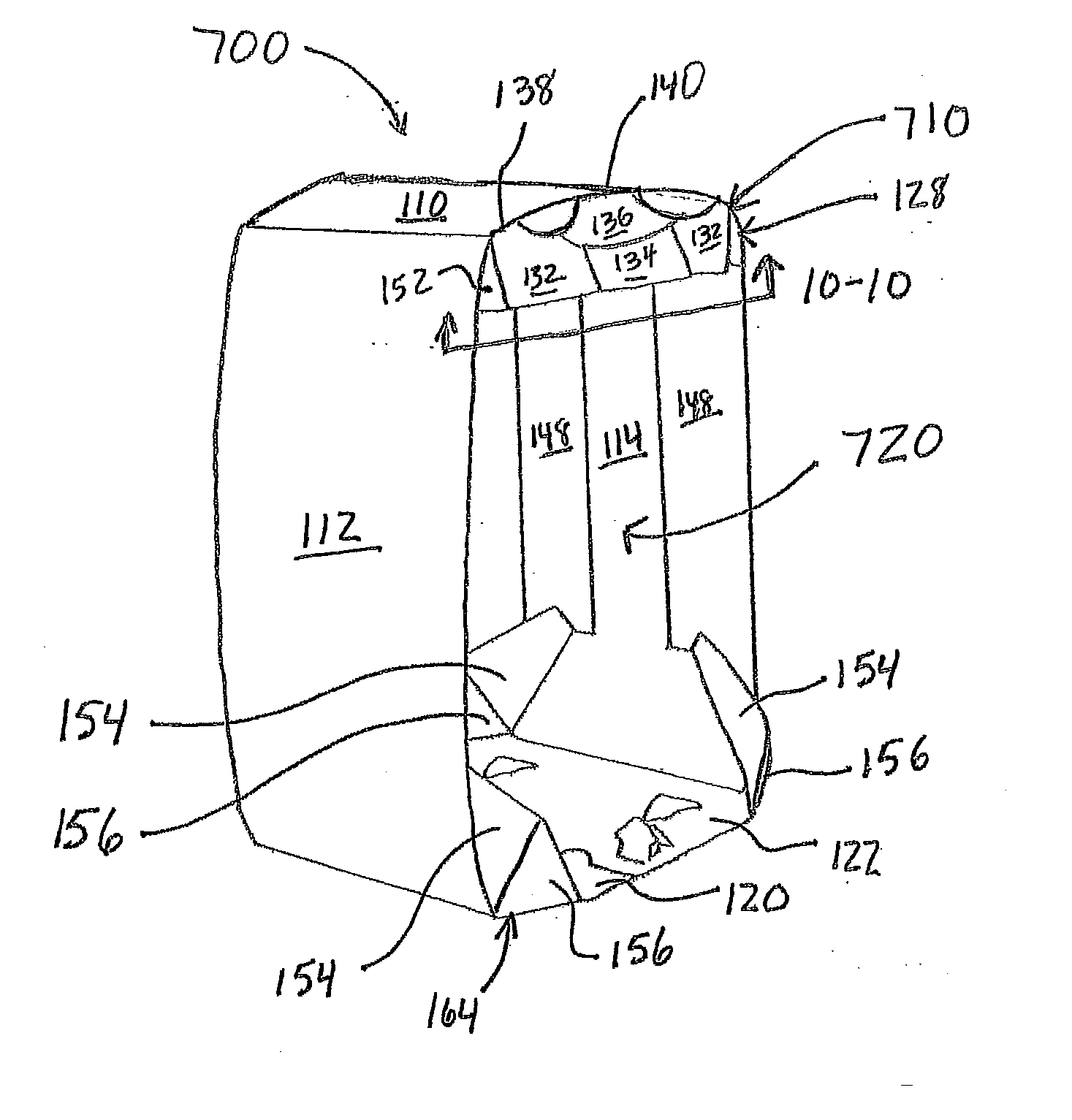
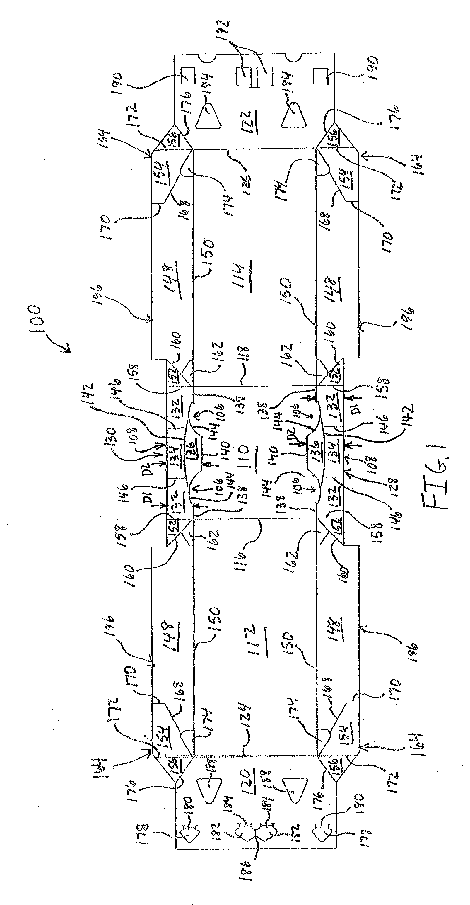
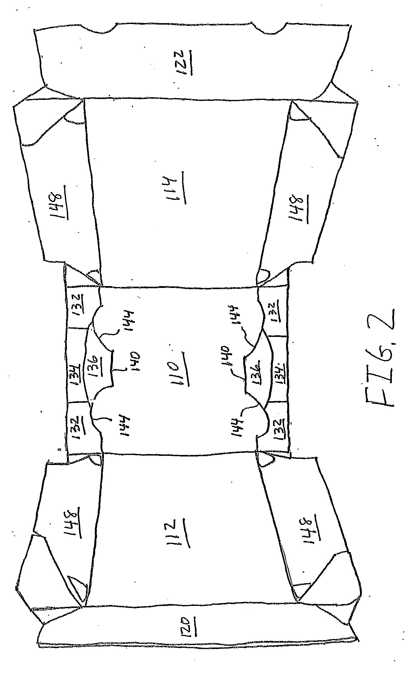
Carton with deflectable carry top
a carry-top, open-end technology, applied in the field of cartons, can solve the problems of affecting the appearance of the carton, affecting the design of the carton, so as to facilitate the deflecting of the end flap inward
- Summary
- Abstract
- Description
- Claims
- Application Information
AI Technical Summary
Benefits of technology
Problems solved by technology
Method used
Image

Examples
Embodiment Construction
[0024] As required, detailed embodiments of the present invention are disclosed herein. It must be understood that the disclosed embodiments are merely exemplary of the invention that may be embodied in various and alternative forms, and combinations thereof. As used herein, the word “exemplary” is used expansively to refer to embodiments that serve as illustrations, specimens, models, or patterns. The figures are not necessarily to scale and some features may be exaggerated or minimized to show details of particular components. In other instances, well-known components, systems, materials, or methods have not been described in detail in order to avoid obscuring the present invention. Therefore, specific structural and functional details disclosed herein are not to be interpreted as limiting, but merely as a basis for the claims and as a representative basis for teaching one skilled in the art to variously employ the present invention.
[0025] Referring now to the drawings in which l...
PUM
 Abstract
Description
Claims
Application Information