Clip

a clip and two-piece technology, applied in the field of clips, can solve the problems of unfavorable deflection of one end side of resilient beams, and insufficient expansion force naturally

Inactive Publication Date: 2005-05-05
PIOLAX CO LTD
View PDF11 Cites 10 Cited by
  • Summary
  • Abstract
  • Description
  • Claims
  • Application Information

AI Technical Summary

Benefits of technology

[0014] Therefore, in the invention according to the first aspect, in the case where the total plate thickness of the plate-like members which are fixed is large, the plate-like members are reliably clamped by portions of the collar of the grommet and the fully expanded expansion leg pieces. On the other hand, in the case where the total plate thickness of the plate-like members which are fixed is small, the plate-like members are reliably clamped by the collar of the grommet and the resilient beams which project outwardly of the expansion leg pieces on the collar side. In either case, therefore, it becomes possible to firmly fix the plate-like members without rattling.
[0015] In the invention according to the second aspect, since the resilient beam has one ends connected to the collar and the other ends integrally connected to each other, it becomes possible for the resilient beams to easily deflect in the slits. In the invention according to the third aspect, since the other ends of the resilient beams project outwardly in a tapered shape, the operation of pushing of the plate-like member into the attaching hole can be effected smoother. In consequence, since the size of the resilient beams becomes long, the resilient beams are made further deflectable. In the invention according to the fourth aspect, since the jutting out shoulders of the resilient beams are actively involved in the fixation of the plate-like members, the state of fixation of the plate-like members is made firmer.
[0016] In the invention according to the fifth aspect, since the pairs of jutting out shoulders are formed at vertically different positions, it becomes correspondingly possible to cope with a number of kinds of thin plates. In the invention according to the sixth aspect, since the pin has accommodating grooves or accommodating the resilient beams, particularly in the case where a thick plate is made an object, the resilient beams themselves which project outwardly of the expansion leg pieces, or their jutting out shoulders, do not constitute hindrances. In the invention according to the seventh aspect, since the collar has open ports on the outer sides of the one ends of the resilient beams, the deflection of the one end side of the resilient beams is facilitated. In particular, in cases where jutting out shoulders are molded on the outer surfaces of the resilient beams, it becomes possible to utilize these open ports as mold insertion ports.

Problems solved by technology

However, in a case where the total plate thickness of the plate-like member and the body panel is conversely small, the expanding force naturally becomes insufficient in the light of the fact that the expansion leg pieces must expand on the root side of the collar.
Therefore, in the event that a large external force is applied or the effect of vibrations persists for a long time after the fixation of the plate-like member, there has been a possibility that the plate-like member rattles unexpectedly, or unpleasant noise occurs due to the rattling.
It should be noted that, in the conventional clip, a construction is adopted in which expanding points of the expansion leg pieces are made different in the axial direction, with this measure alone it has not been impossible to expect a sufficient effect.

Method used


Image

  • Clip
  • Clip
  • Clip

Examples


Embodiment Construction

[0033] In the invention, in a two-piece type clip comprised of a pin and a grommet, particularly even in a case where the total plate thickness of plate-like members which are fixed is small, the plate-like members can be reliably fixed without rattling by making improvements on the grommet side.

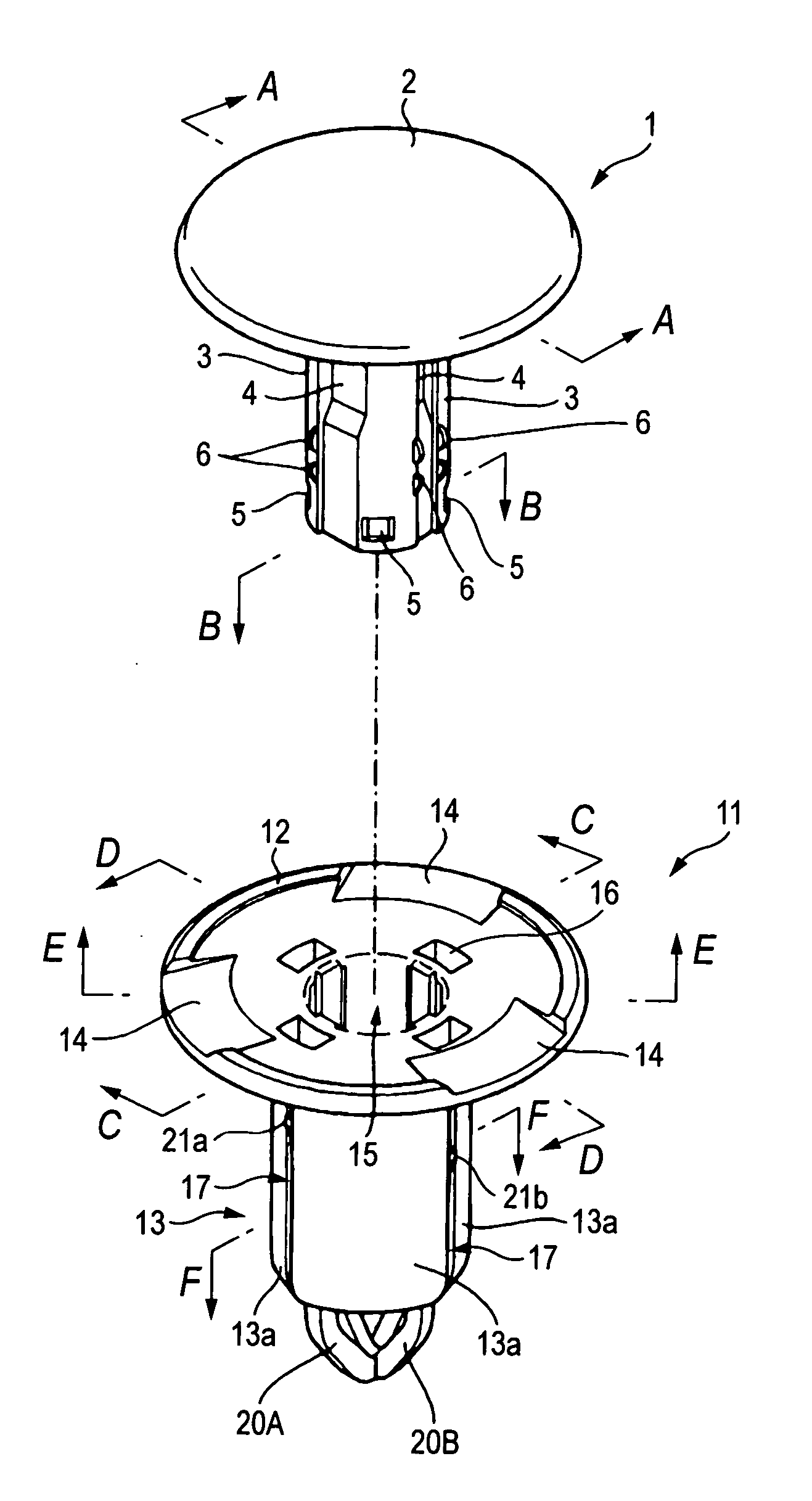
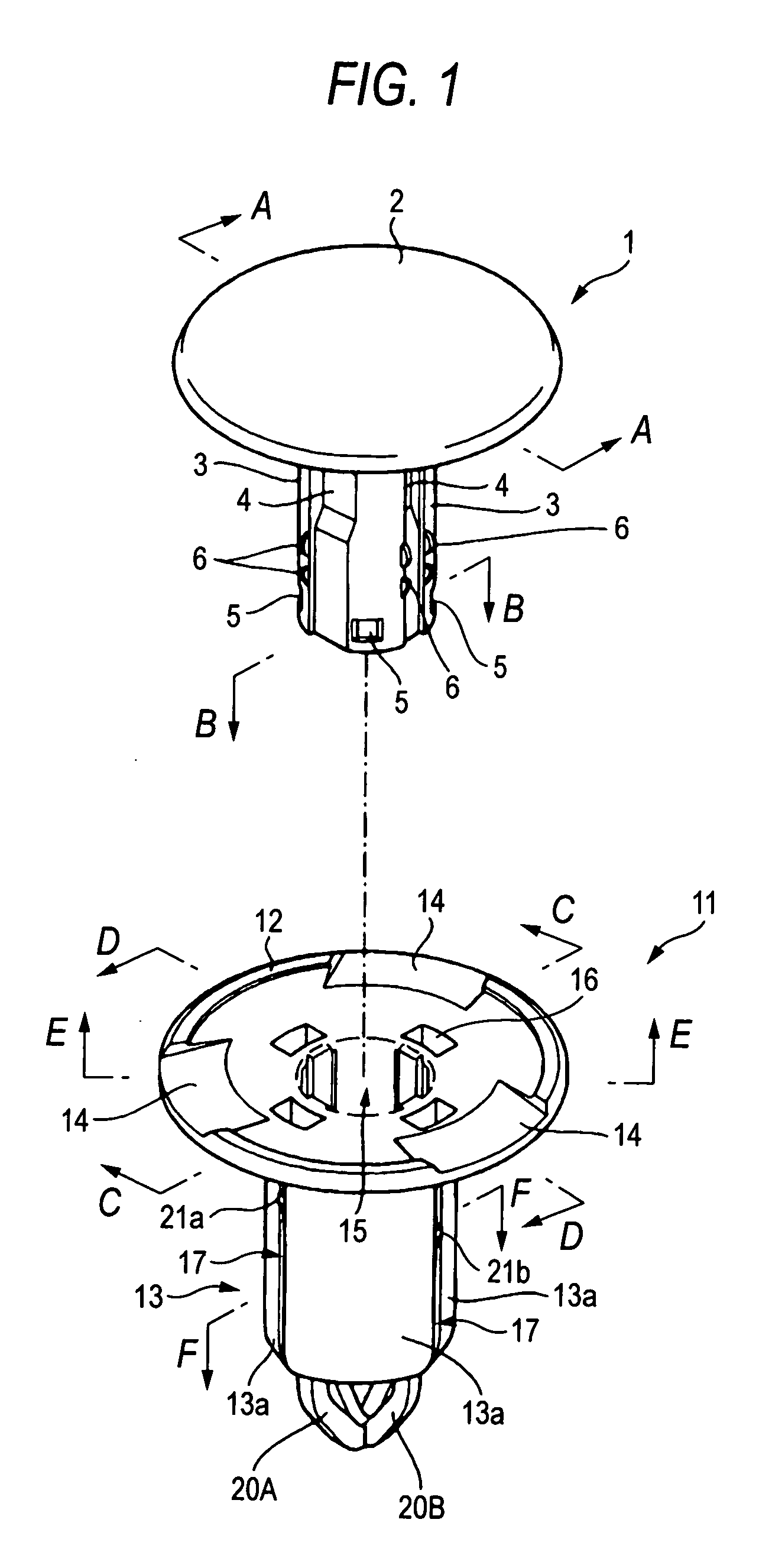
[0034] Hereafter, a detailed description will be given of a preferred embodiment of the invention illustrated in the drawings. As shown in FIG. 1, the clip in accordance with this embodiment is comprised of two parts including a pin 1 and a grommet 11, which are integrally molded from a synthetic resin, and is used for fixing a plate-like member, such as an interior or exterior part of an automobile, to a vehicle body panel.

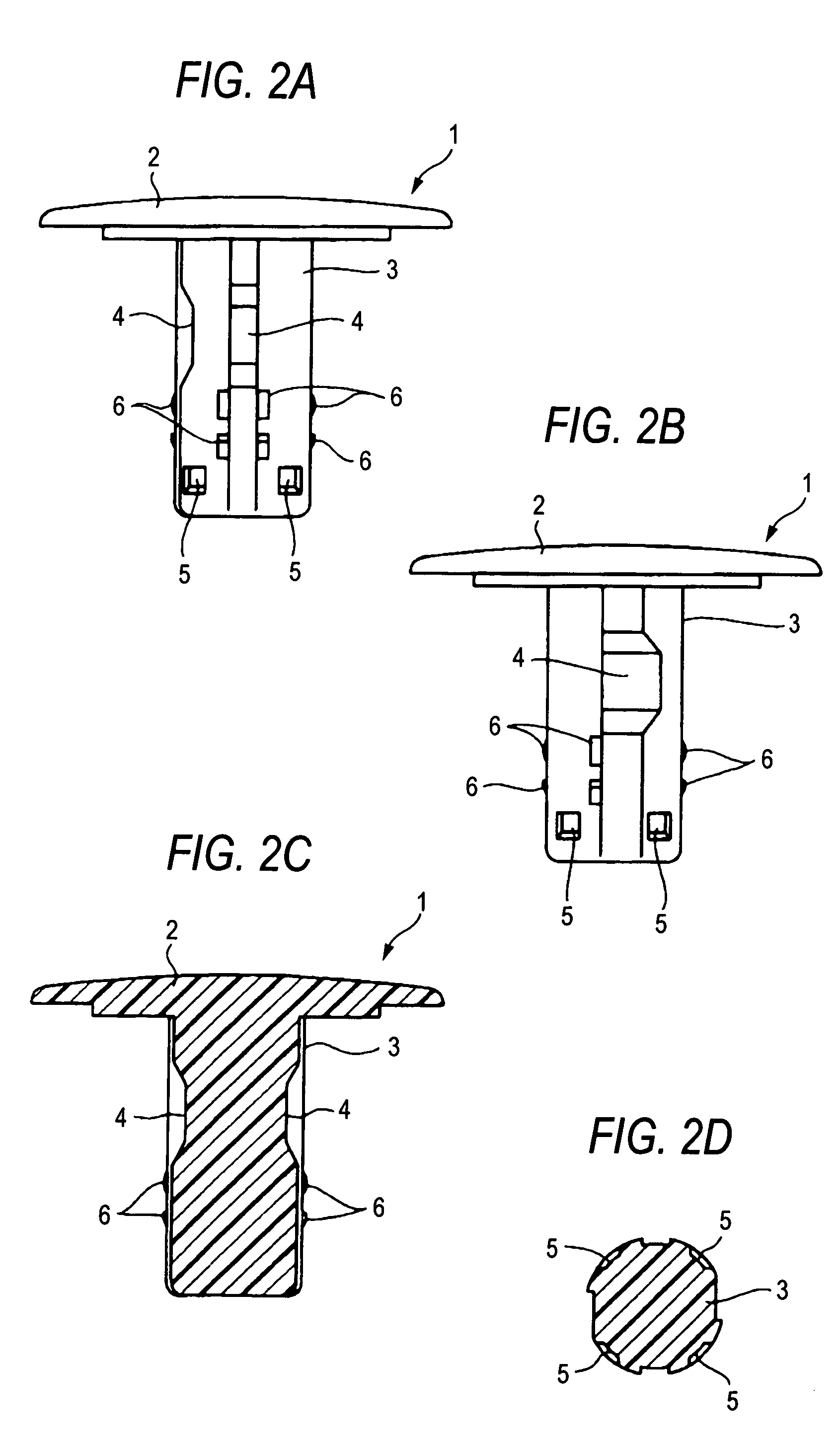
[0035] To give a specific description, the first-mentioned pin 1 has a disk-shaped head 2 and a cylindrical shank 3 suspended from a lower surface of the head 2. In particular, as also shown in FIGS. 2A to 2D, four accommodating grooves 4 for accommodating resilient bea...


PUM


Abstract

A clip includes: a pin having a head and a shank; and a grommet having a collar and a leg. The leg of the grommet is divided into a plurality of expansion leg pieces by means of slits extending along an axial direction. The expansion leg pieces of the leg are expanded outwardly by the insertion of the pin into an inner side of the grommet, so as to clamp plate-like members by the collar and the expansion leg pieces. The leg of the grommet has resilient beams which project outwardly of the expansion leg pieces on a collar side when the pin is inserted into the inner side of the grommet.

Description

BACKGROUND OF THE INVENTION [0001] 1. Field of the Invention [0002] The present invention relates to a two-piece type clip for fixing a plate-like member, such as an interior or exterior part of an automobile, to a vehicle body panel, for example. [0003] 2. Description of the Related Art [0004] Each conventional clip of this type, although not specifically shown, is comprised of two parts including a pin and a grommet, which are integrally molded from a synthetic resin. The former pin has a head and a shank, while the latter grommet has a collar and a leg, the leg being divided into a plurality of expansion leg pieces by means of slits extending along an axial direction (refer to, for example, JP-A-11-270525). [0005] When a plate-like member of an automobile is actually fixed to a body panel, the shank of the pin is first inserted into inner sides of the expansion leg pieces through an opening formed in the collar of the grommet, thereby obtaining a state in which the two members ar...

Claims


Application Information

Patent Timeline
Patent Type & Authority Applications(United States)
IPC IPC(8): B62D27/02F16B19/10
CPCB62D27/02Y10T24/42Y10T24/309F16B19/1081
Inventor KOIKE, TAKASHI
Owner PIOLAX CO LTD
Why Eureka
Try Eureka