Suture passer devices and methods

a technology of suture passage and passor, which is applied in the field of suture passage devices and methods, can solve the problems of undesirable access to tissue in this manner, time-consuming suction of tissue during surgical procedures, and difficulty in particular, and achieve the effect of limited travel distance of tissue penetrator

Active Publication Date: 2012-11-08
CETERIX ORTHOPAEDICS
View PDF31 Cites 38 Cited by
  • Summary
  • Abstract
  • Description
  • Claims
  • Application Information

AI Technical Summary

Benefits of technology

[0026]The motion of the tissue penetrator may be regulated to prevent the tissue penetrator from extending beyond the opening formed between the first and second jaw members as it extends across this opening. In particular, a dual deployment suture passer may be configured to prevent the tip of the tissue penetrator from extending beyond the outside of a jaw member. Extending beyond the jaw member may result in damage to surrounding (non-target) tissues. For example, the suture passer may be configured so that the extent of travel of the tissue penetrator is limited based on how “open” the jaw members are; in variations in which the size of the opening can be modified by adjusting the angle of the first jaw member relative to the elongate body of the device, a limiter may prevent the tissue penetrator from extending further beyond the side of a jaw member opposite from the jaw member housing the tiss

Problems solved by technology

Suturing of tissue during surgical procedures is time consuming and can be particularly challenging in difficult to access body regions and regions that have limited clearance, such as regions partially surrounded or covered by bone.
However, in many cases, accessing the tissue in this manner is undesirable, increasing recovery time, and exposing the patient to greater risk of infection.
Although many such devices are available for endoscopic and/or percutaneous use, these devices suffer from a variety of problems, including limited ability to navigate and be operated within the tight confines of the body, risk of injury to adjacent structures, problems controlling the position and/or condition of the tissue before, during, and after passing the suture, as well as problems with the reliable functioning of the suture passer.
For example, some surgical instruments used in endoscopic procedures are limited by the manner in which they access the areas of the human body in need of repair.
In particular, the instruments may not be able to access tissue or organs located deep within the body or that are in some way obstructed.
In addition, many of the instruments are limited by the way they grasp tissue, apply a suture, or recapture the needle and suture.
Furthermore, many of the instruments are complicated and expensive to use due to the numero

Method used


Image

  • Suture passer devices and methods
  • Suture passer devices and methods
  • Suture passer devices and methods

Examples


Embodiment Construction

[0080]Described herein are suture passers. In general, these devices may be referred to herein as suture passers, suturing devices. The devices described herein may also be referred to as dual deployment suture passers, or in some variations, clamping / sliding suture passers.

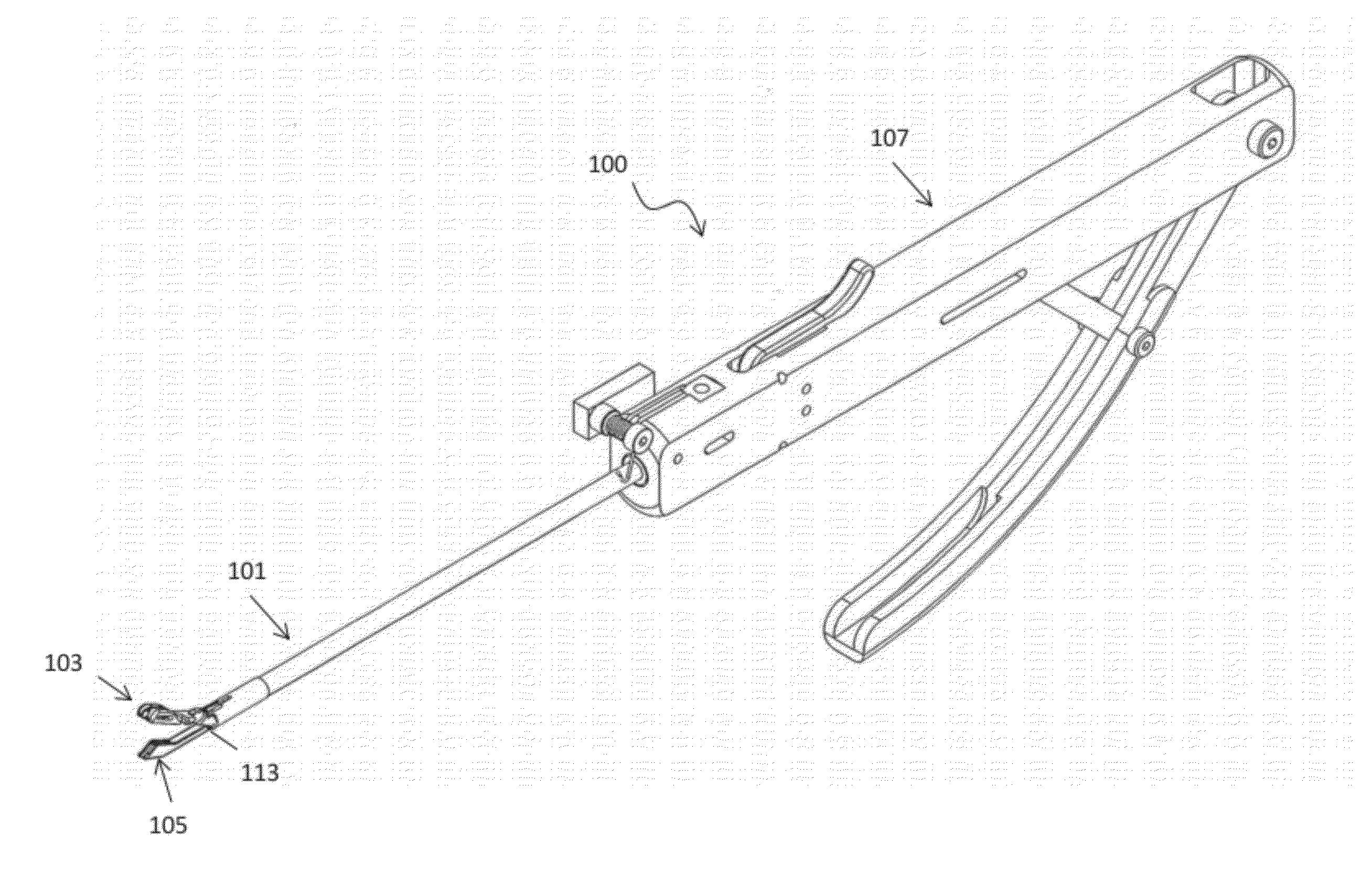
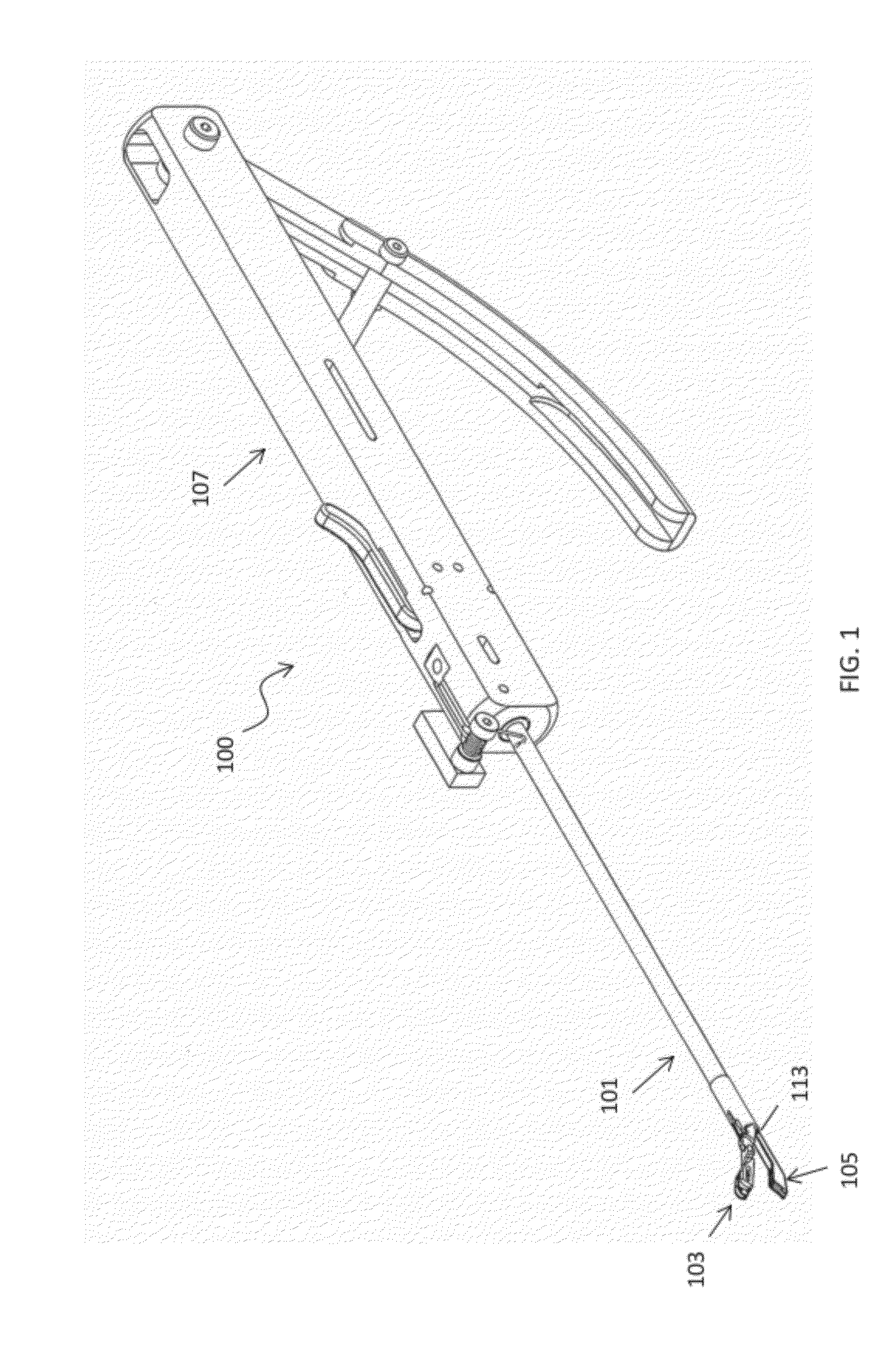
[0081]In general, the suture passers described herein include a first jaw member and second jaw member that are configured to extend from the end of an elongate body region. FIG. 1 illustrates one variation of a dual deployment suture passer 100. In this example, the device has a first (upper) jaw member 103 extending distally from the distal end of a more proximal elongate member 101. A second jaw member 105 is shown extended distally beneath the first jaw member 105. A handle 107 is located at the proximal end of the device and includes multiple controls for independently controlling the movements of the first jaw member, second jaw member, and tissue penetrator. The handle in this example also includes a secon...


PUM


Abstract

Devices, systems and methods for passing a suture. In general, described herein are suturing devices, such as suture passers, as well as methods of suturing tissue. These suture passing devices are dual deployment suture passers in which a first distal jaw member is moveable at an angle with respect to the longitudinal axis of the elongate body of the device and the second distal jaw member is retractable proximally to the distal end region of the elongate body and/or the first jaw member. Methods of suturing tissue using a dual deployment suture passer are also described.

Description

CROSS REFERENCE TO RELATED APPLICATIONS[0001]This patent application claims the benefit of priority to the following provisional patent applications: U.S. Provisional Patent Application No. 61 / 483,200, titled “MENISCUS REPAIR”, filed on May 6, 2011, and U.S. Provisional Patent Application No. 61 / 511,922, titled “MENISCUS REPAIR”, filed on Jul. 26, 2011.[0002]This patent application may be related to U.S. patent application Ser. No. 12 / 942,803, titled “DEVICES, SYSTEMS AND METHODS FOR MENISCUS REPAIR”, filed on Nov. 9, 2010, which claim priority to U.S. Provisional Patent Application Nos.: 61 / 259,572, titled “DEVICES, SYSTEMS EMS AND METHODS FOR MENISCUS REPAIR”, filed on Nov. 9, 2009; 61 / 295,354, titled “DEVICES, SYSTEMS AND METHODS FOR MENISCUS REPAIR”, filed on Jan. 15, 2010; and 61 / 318,215, titled “CONTINUOUS SUTURE PASSERS HAVING TISSUE PENETRATING SUTURE SHUTTLES”, filed on Mar. 26, 2010.[0003]All of these applications are herein incorporated by reference in their entirety.INCO...

Claims


Application Information

Patent Timeline
IPC IPC(8): A61B17/04
CPCA61B17/0469A61B17/0482A61B17/0485A61B17/062A61B17/0625A61B2017/2927A61B2017/0496A61B2017/06009A61B2017/06014A61B2017/06042A61B2017/06176A61B2017/0472A61B17/04A61B17/11
Inventor SALIMAN, JUSTIN D.MCCUTCHEON, JOHN G.BENDER, CHRIS P.HIROTSUKA, MARK Y.MURILLO, MICHAELHENDRICKSEN, MICHAEL J.
Owner CETERIX ORTHOPAEDICS
Why Eureka
Try Eureka