
Syringe Assembly Having a Telescoping Plunger Rod

a telescopic, plunger rod technology, applied in the field of prefilled syringe assemblies, can solve the problems of risk, limited space within the controlled storage location, and the storage space required for containing this syringe, and achieve the effect of facilitating the removal of the molded cover

Active Publication Date: 2013-04-04
BECTON DICKINSON FRANCE
View PDF6 Cites 32 Cited by
  • Summary
  • Abstract
  • Description
  • Claims
  • Application Information

AI Technical Summary

Benefits of technology

The present invention relates to a telescopic plunger rod assembly for use with a syringe assembly. The plunger rod can transition from a collapsed position to an extended position and includes one or more stop members that limit its outward travel from the syringe barrel. The plunger rod is lockable to the inner member of the syringe assembly using a laterally extending member and a locking member. The invention also includes a packaging assembly with a molded cover that protects the plunger rod from accidental transition to its extended position. The technical effects of the invention are to provide a safer and more stable syringe assembly that can be easily packaged and used for injection purposes.

Problems solved by technology

The space within these controlled storage locations is often limited, thus there is a need for a syringe assembly that has a smaller packaging footprint, to reduce the storage space required for containing this syringe.
Even though measures, such as controlled storage, are taken to ensure the contents of these syringes remain intact, the risk still remains that the syringe contents can be tampered with and / or stolen and replaced with a saline solution.

Method used


Image

  • Syringe Assembly Having a Telescoping Plunger Rod
  • Syringe Assembly Having a Telescoping Plunger Rod
  • Syringe Assembly Having a Telescoping Plunger Rod

Examples


Embodiment Construction

[0032]For purposes of the description hereinafter, the terms “upper”, “lower”, “right”, “left”, “vertical”, “horizontal”, “top”, “bottom”, “lateral”, “longitudinal”, and derivatives thereof shall relate to the invention as it is oriented in the drawing figures. However, it is to be understood that the invention may assume various alternative variations, except where expressly specified to the contrary. It is also to be understood that the specific devices illustrated in the attached drawings, and described in the following specification, are simply exemplary embodiments of the invention. Hence, specific dimensions and other physical characteristics related to the embodiments disclosed herein are not to be considered as limiting.

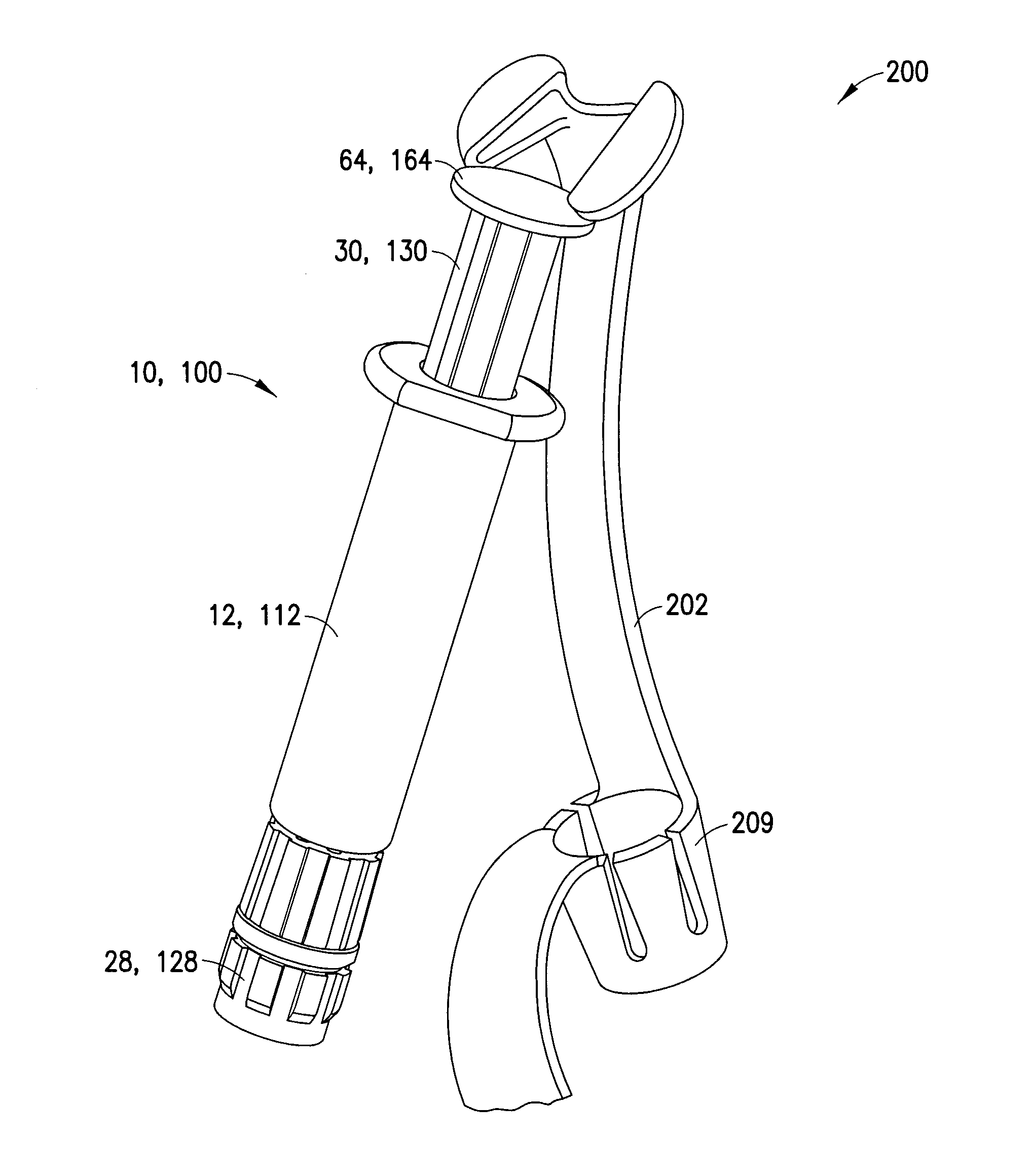
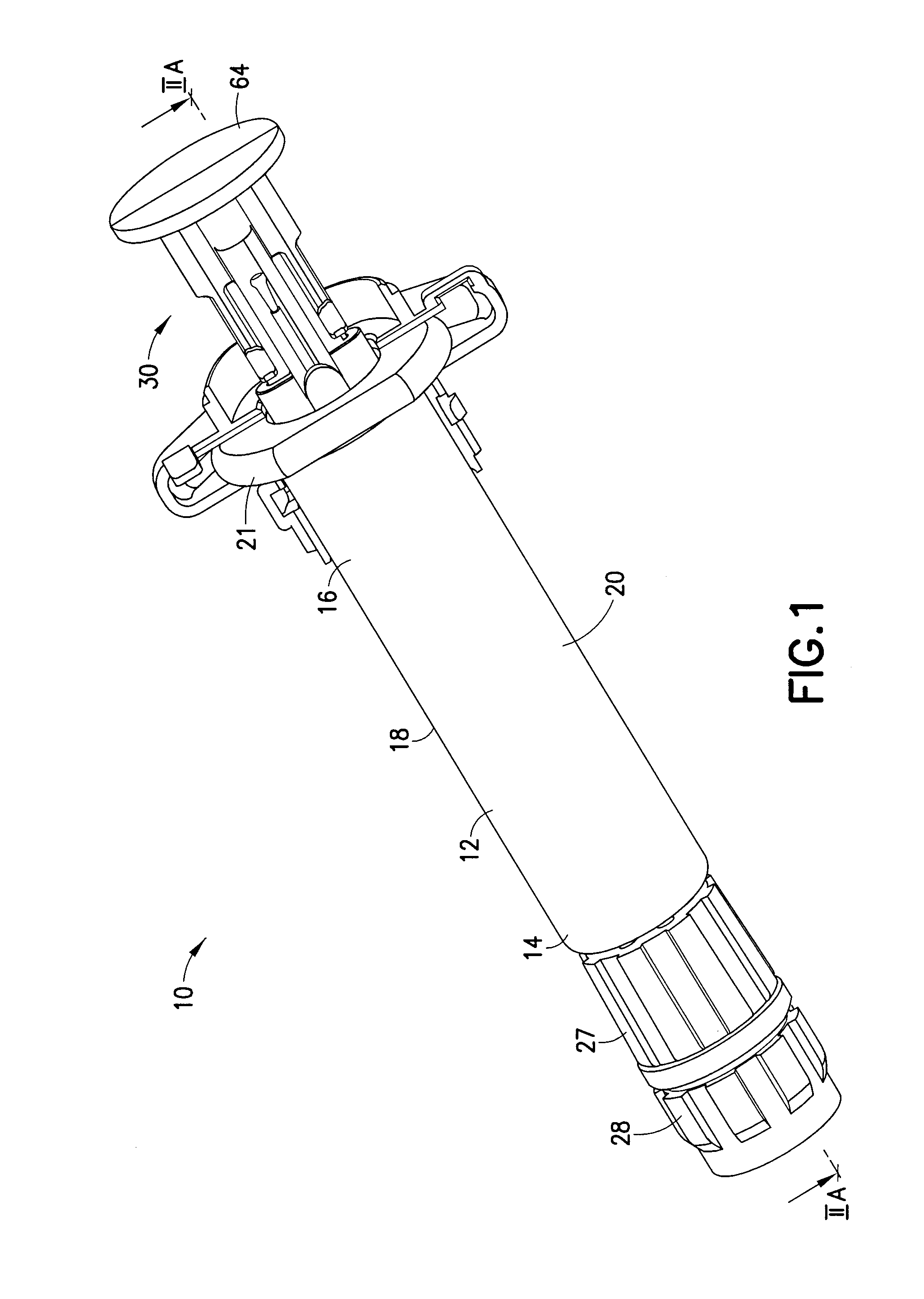
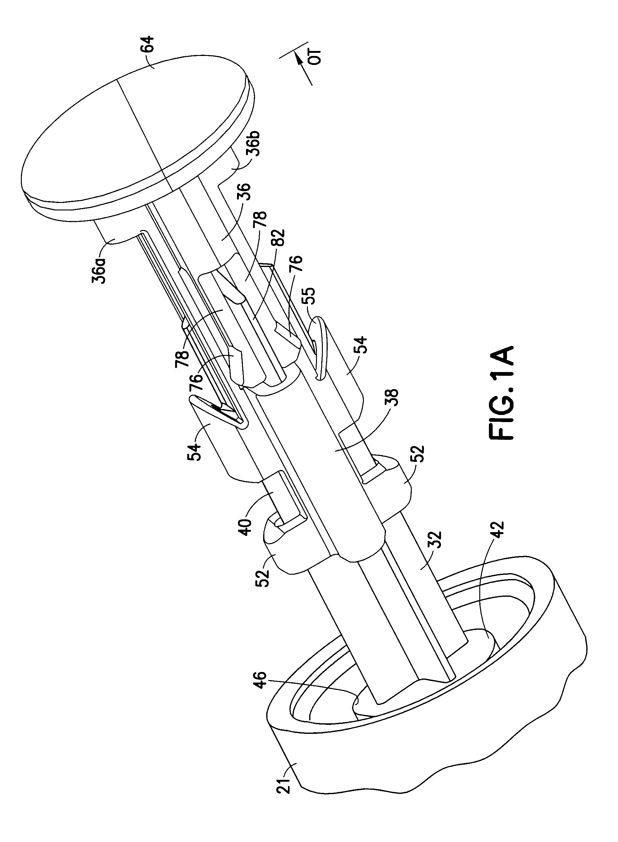
[0033]Reference is now made to FIGS. 1, 1A-1B, 2A-2B, 3, 4A-4B, and 5A-5B, which depict a syringe assembly according to an embodiment of the present invention, generally indicated as 10, adapted for the dispensing and delivery of a fluid. FIGS. 6A-6B and 7A-7...


PUM


Abstract

A syringe assembly including a syringe barrel having a first end, a second end, and a sidewall extending therebetween defining a chamber is disclosed. The syringe assembly includes a stopper disposed within the chamber of the syringe barrel and a plunger rod having an inner member engaged with the stopper and an outer member adapted for telescopic movement with respect to the inner member. The plunger rod is transitionable from a collapsed position, in which a portion of the inner member is nested within the outer member, to an extended position, in which the same portion of the inner member extends outside the outer member. The syringe assembly also includes a stop member configured for cooperation with a portion of the syringe barrel, upon relative movement of the outer member with respect to the inner member, to limit the outward travel of the plunger rod from the syringe barrel.

Description

CROSS-REFERENCE TO RELATED APPLICATION[0001]This application claims priority to U.S. Provisional Application Ser. No. 61 / 541,658 filed Sep. 30, 2011, the entire disclosure of which is hereby incorporated by reference.BACKGROUND OF THE INVENTION[0002]1. Field of the Invention[0003]The present invention is directed to a pre-filled syringe assembly adapted for the dispensing and delivery of a fluid. More particularly, the present invention is directed to a pre-filled syringe assembly having a telescopic plunger rod having a pull-out safety arrangement wherein the plunger rod arrangement results in a smaller packaging footprint allowing for reduced storage space. The present invention is also directed to a packaging system for a pre-filled syringe assembly that prevents unintended actuation of the plunger rod and reduces the likelihood of tampering of the syringe contents.[0004]2. Description of Related Art[0005]Conventional syringes are well known to be used in connection with a vial o...

Claims


Application Information

Patent Timeline
Patent Type & Authority Applications(United States)
IPC IPC(8): A61M5/315B65D17/34
CPCA61M5/31511A61M2005/31518A61M2005/3104A61M5/5086A61M5/002
Inventor SCHIFF, DAVID ROBERTTURPAULT, MATHIEU DOMINICGATTA, ANTONIOCOLEMAN, JOHN DEPLER
Owner BECTON DICKINSON FRANCE
Learn More