Bracelet clasp comprising a sliding catch

a clasp and sliding technology, applied in the field of clasps with sliding catch, can solve the problems of not having the abovementioned disadvantage of devices, not ensuring the joining of two strands, and difficult to envisag

Inactive Publication Date: 2009-05-28
MEIER BT
View PDF2 Cites 34 Cited by
  • Summary
  • Abstract
  • Description
  • Claims
  • Application Information

AI Technical Summary

Benefits of technology

[0016]In another particularly advantageous variant, the band is furnished with a first guide, the clasp comprises first and a second slide-blocks moving in this first guide on either side of the member for limiting the travel of the band in the closed position. The first and second slide-blocks each form a second guide. The closing elements each comprise a skid interacting respectively with the second guide of the first and second slide-blocks, to allow the relative movement of the elements and of the band.

Problems solved by technology

Such a rather rudimentary structure certainly prevents the complication of an unfolding catch, but it does not guarantee that the two strands will remain joined when a considerable force is applied to the bracelet which may therefore open inadvertently.
However, this device does not have the abovementioned disadvantage because this end is furnished with two fingers forming a Y, these fingers preventing the band from coming right out of the strand in which it is lodged.
However, since the band slides in only one strand, it is difficult to envisage that the conditions of sliding inside the band can be appropriate over a great length, because the flexing that the band sustains causes major friction between it and the bracelet.
In addition, the bracelet, necessarily being hollow and rigid to allow the band to slide, is not very comfortable for the wearer.
Actually, such a device cannot be adapted to flexible bracelets made of leather, rubber or even of metal with articulated links.

Method used


Image

  • Bracelet clasp comprising a sliding catch
  • Bracelet clasp comprising a sliding catch
  • Bracelet clasp comprising a sliding catch

Examples


Embodiment Construction

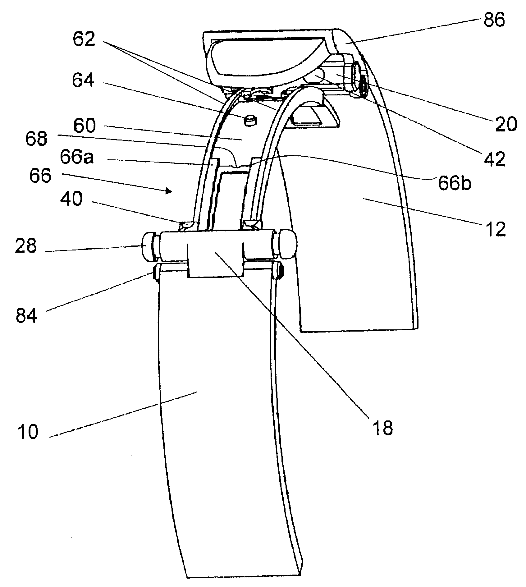
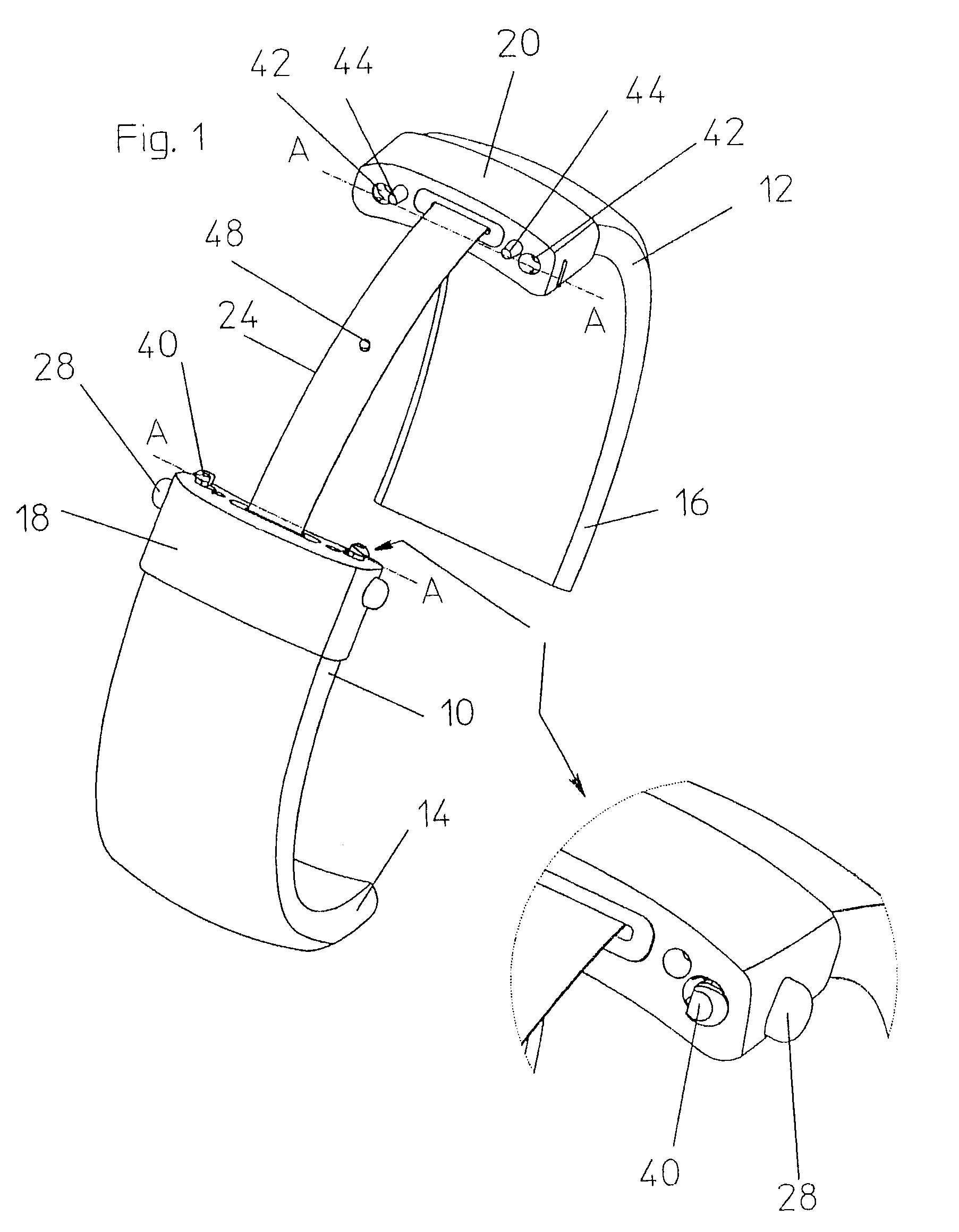
[0025]A bracelet having a clasp comprising a sliding catch according to the invention, in the open position, is represented in FIG. 1 showing only that it comprises two strands 10 and 12. It is understood that, for a watch application, it effectively involves two separate strands whose respective ends 14 and 16 are suitable for being connected to a watch case by any method known to those skilled in the art. On the other hand, for a jewelry application, the bracelet may comprise either a single strand, or two strands joined by a central articulation. The bracelet represented has links, but it may be monobloc, particularly made of synthetic material.

[0026]The invention relates essentially to the clasp that makes it possible to couple the ends of the bracelet opposite to the ends 14 and 16.

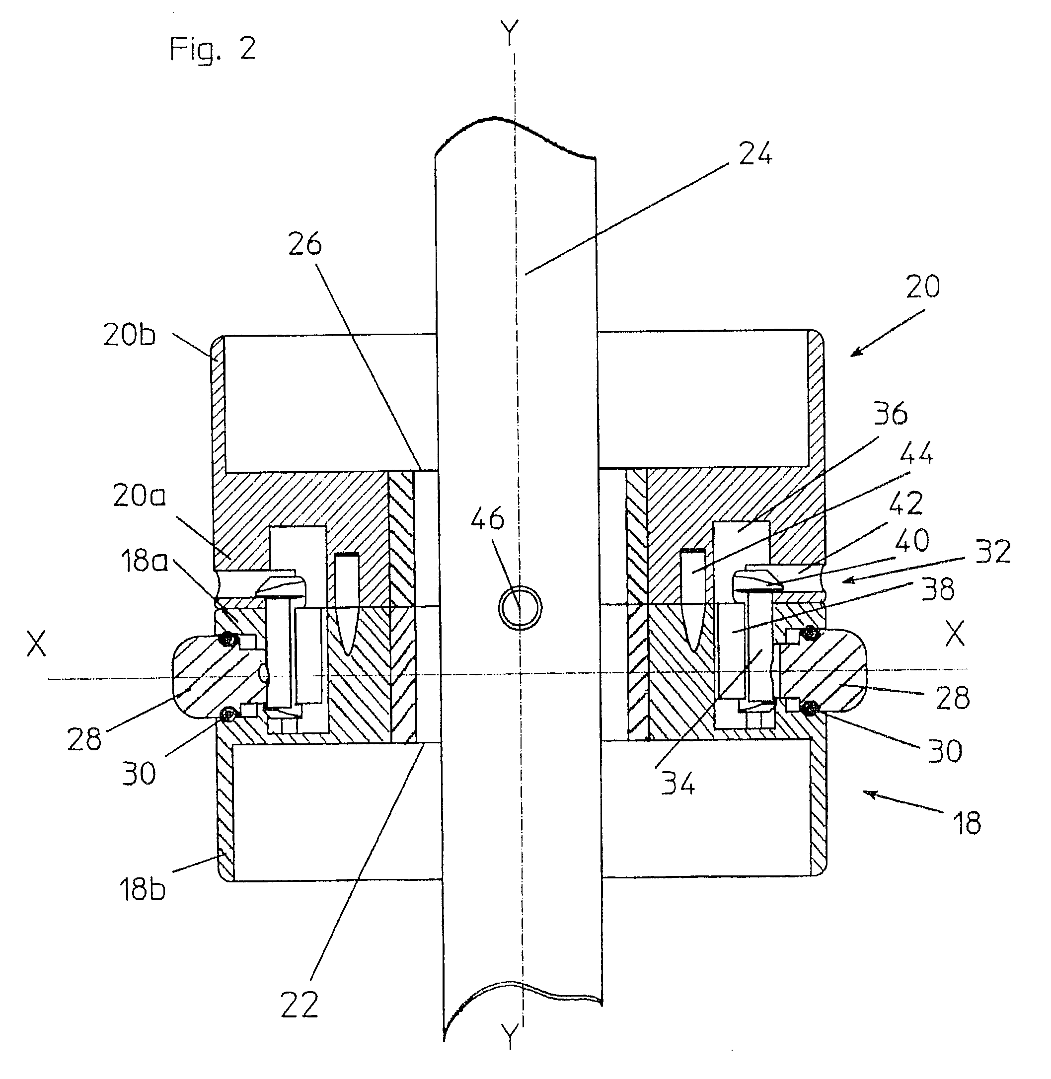
[0027]FIGS. 1 and 2 show that the two strands 10 and 12 are attached, by their respective ends, to two elements 18 and 20 that form the actual clasp of the bracelet and have the same outer, generally...


PUM


Abstract

A bracelet clasp having two closing elements (18,20) arranged on the two ends of a bracelet to be joined thereby and provided with means (28, 40, 42) for the coupling thereof. A band (24, 60) is used to connect the elements and is mounted in such a way that it can be displaced in relation to both elements. Devices are provided for defining the course of band displacement in relation to the open position of the closing elements, and for associating one end of the band with one of the closing elements. The clasp also has a device for defining the course of band displacement in relation to the closed position of the closing elements, this device being arranged on a central portion of the band in relation to its length between the closing elements in their open position.

Description

TECHNICAL FIELD[0001]The present invention relates to a clasp with a sliding catch designed to be fitted to a bracelet of the closed type that can be used both in watches and in jewelry but also, more generally, as any type of collar designed to be placed about a body, in a removable manner.BACKGROUND[0002]Bracelets are either of the open type, when their two strands can be completely separated, or of the closed type, when the strands remain fixedly attached and are connected to one another by a clasp making it possible to increase their diameter in order to be able to put the hand through.[0003]Bracelets of this second type, to which the invention applies, most frequently use a catch, called an unfolding catch, that usually comprises a clasp with two bands articulated in butterfly fashion. In the closed position, the bands are kept folded over one another. Actuating the clasp allows them to unfold and therefore enlarge the bracelet.[0004]Certain less frequent embodiments of bracele...

Claims


Application Information

Patent Timeline
Patent Type & Authority Applications(United States)
IPC IPC(8): A44C5/18
CPCA44C5/22A44C5/0069
Inventor STAMPFLI, ROLANDMEIER, WILLY
Owner MEIER BT
Why Eureka
Try Eureka