Ophthalmic lens combinations

Inactive Publication Date: 2006-10-26
ABBOTT MEDICAL OPTICS INC
View PDF99 Cites 187 Cited by
  • Summary
  • Abstract
  • Description
  • Claims
  • Application Information

AI Technical Summary

Benefits of technology

[0011] New combinations of ophthalmic devices such as intraocular lens combinations (ILCs) have been disclosed. Embodiments of the present invention provide distance, near and/or intermediate vision by axially moving and/or deforming one or more optical elements, for example, by deforming at least one optical surface (e.g., changing a radius of curvature or conic constant of the surface) and/or changing the thickness of the optic. The present combinations may be used to enhance the degree of accommodation achieved in spite of the movement and space limitations within the eye and to produce near and/or distant vision that is relatively low in optical aberrations. One advantage of the present combinations is the ability to standardize the prescription or optical power of the accommodating lens or optic of the combination. Thus, the required amount of movement and/or deformation in the eye to achieve accommodation can be substantially the same for all pati

Problems solved by technology

Such a conventional IOL has very limited, if any, accommodating ability.
However, the wearer of such an IOL continues to require the ability to view both near and far (distant) objects.
One problem that exists with such IOLs is that they often cannot move sufficiently to obtain the desired accommodation.
In addition, the presence of such lenses can result in cell growth from the capsular bag onto the optics of such lenses.
Such cell growth, often referred to as posterior capsule opacification (PCO), can interfere with the clarity of the optic to the detriment of the lens wearer's vision.
Another problem that can occur is that of providing an intraocular lens that provides a predetermined amount of accommodative power for a wide variety of eyes and with

Method used


Image

  • Ophthalmic lens combinations
  • Ophthalmic lens combinations
  • Ophthalmic lens combinations

Examples


Example

DETAILED DESCRIPTION OF THE DRAWINGS

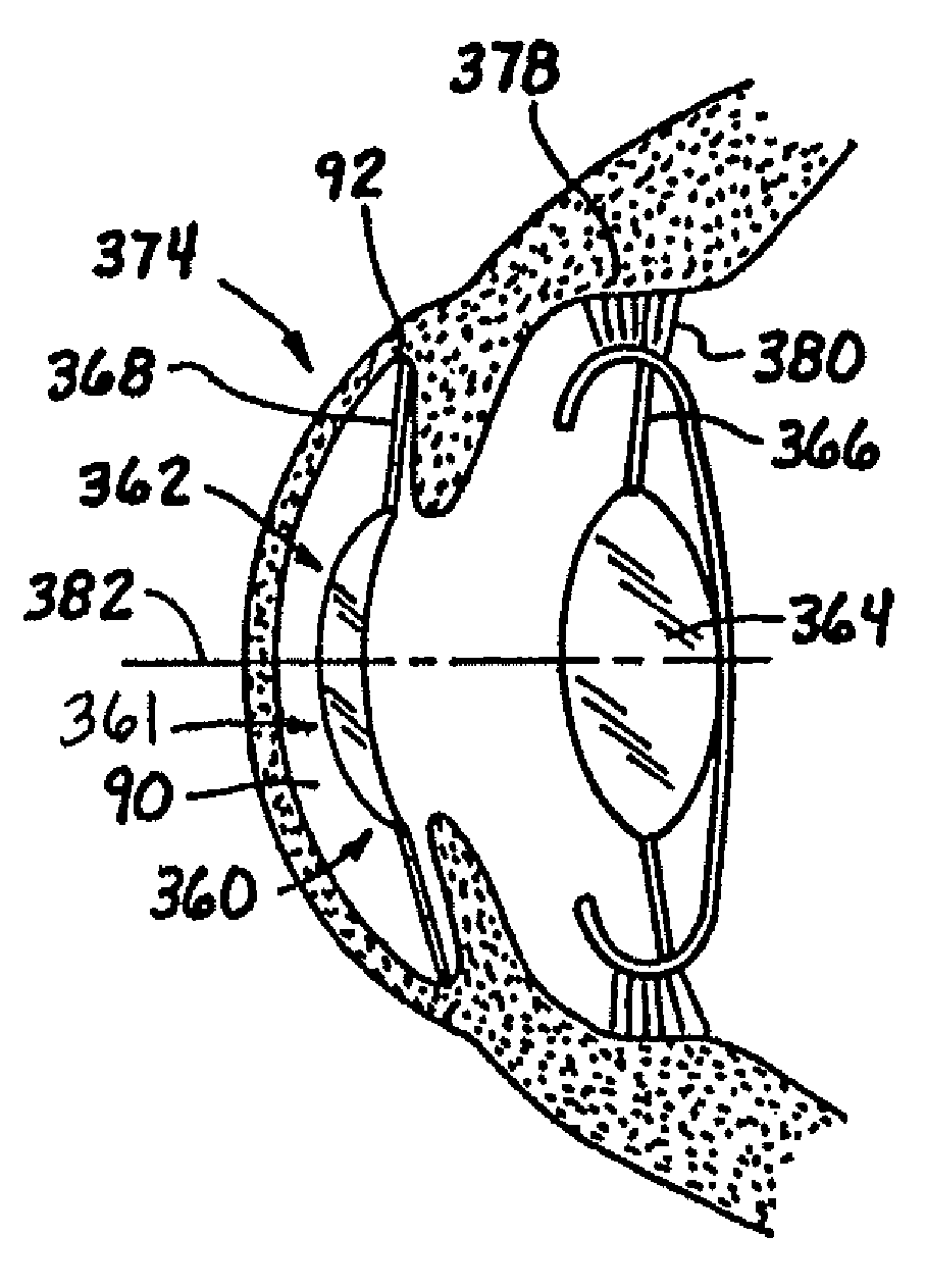
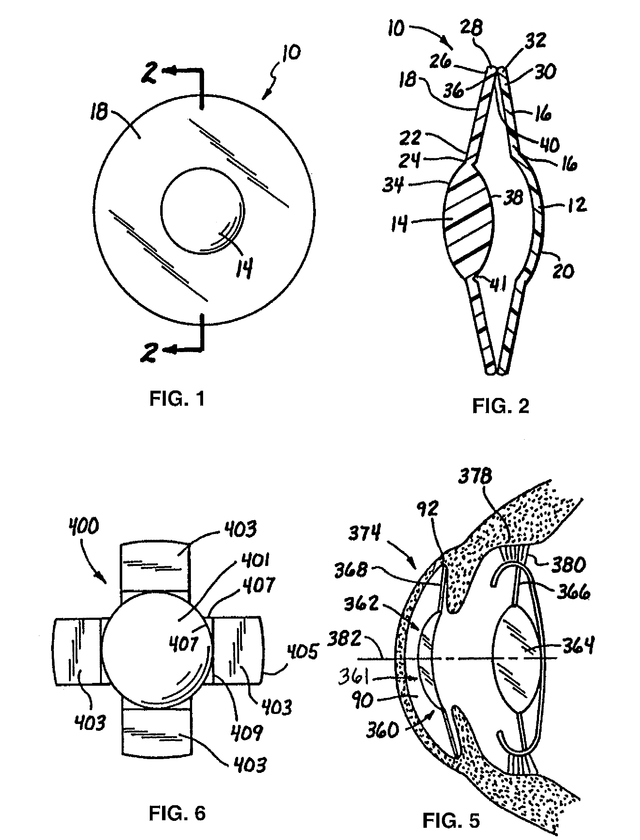
[0056] Referring now to FIGS. 1 and 2, an ILC according to the present invention, shown generally at 10, includes a first optic or optic body 12, a second optic or optic body 14, a disc type fixation member 16 and a disc type movement assembly 18. As used herein, the term “optic” or “optic body” means an optical element that may be used alone or as part of an optical system to produce an image on the retina the eye of a subject. The terms “optic” and “optic body” are used somewhat interchangeable, with the term “optic” emphasizing more the optical characteristics of an optical element and “optic body” referring more to the use an optical element as part of an intraocular lens that may also include, for example, a base element, a movement assembly, or one or more haptics, fixation members, and / or movement members. An optic or optic body may have an optic power to converge or diverge incident light using the principles of refraction, diffraction, a...


PUM


Abstract

An ophthalmic device is provided for a patient that has a basic prescription for distant vision, the ophthalmic device including a primary optic and a supplemental optic. The primary optic is configured for placement in the eye and has a base optical power configured to substantially provide the basic prescription. The supplemental optic has an optical power that is less than the optical power of the primary optic and is configured to provide, in combination with the primary optic, a combined optical power that provides the basic prescription of the patient. In addition, at least one surface of the primary optic is configured to deform in response to an ocular force so as to modify the combined optical power by at least 1 Diopter. The ophthalmic device may further include a movement assembly operably coupled to the primary optic that is structured to cooperate with the eye to effect accommodating deformation of the primary optic in response to an ocular force produced by the eye. The movement assembly may also be configured to provide accommodating axial movement of the primary optic.

Description

RELATED APPLICATION [0001] This application is a Continuation-in-Part Application of U.S. patent application Ser. No. 10 / 234,801, filed Sep. 4, 2002, which is a Continuation-in-Part Application of U.S. patent application Ser. No. 09 / 390,380, filed Sep. 3, 1999, which claims the benefit of U.S. Provisional Application No. 60 / 132,085 filed Apr. 30, 1999. The disclosures of both the provisional application and the non-provisional application are incorporated in their entirety by reference herein.BACKGROUND OF THE INVENTION [0002] 1. Field of the Invention [0003] The present invention relates generally to devices and methods for correcting vision and more particularly to ophthalmic device combinations for providing accommodative vision. [0004] 2. Description of the Related Art [0005] The human eye includes an anterior chamber between the cornea and iris, a posterior chamber including a capsular bag containing a crystalline lens, a ciliary muscle, a vitreous chamber behind the lens conta...

Claims


Application Information

Patent Timeline
IPC IPC(8): G02C7/04
CPCA61F2/1613A61F2/1648A61F2002/009A61F2/1629A61F2/1602A61F2/1635A61F2250/0053G02C7/00
Inventor GLICK, ROBERT E.BRADY, DANIEL G.
Owner ABBOTT MEDICAL OPTICS INC
Why Eureka
Try Eureka