Image editing method
- Summary
- Abstract
- Description
- Claims
- Application Information
AI Technical Summary
Benefits of technology
Problems solved by technology
Method used
Image


Examples
embodiment mode 1
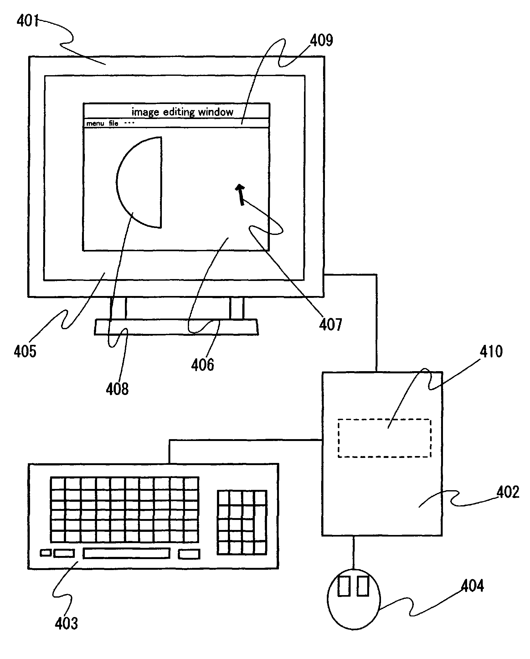
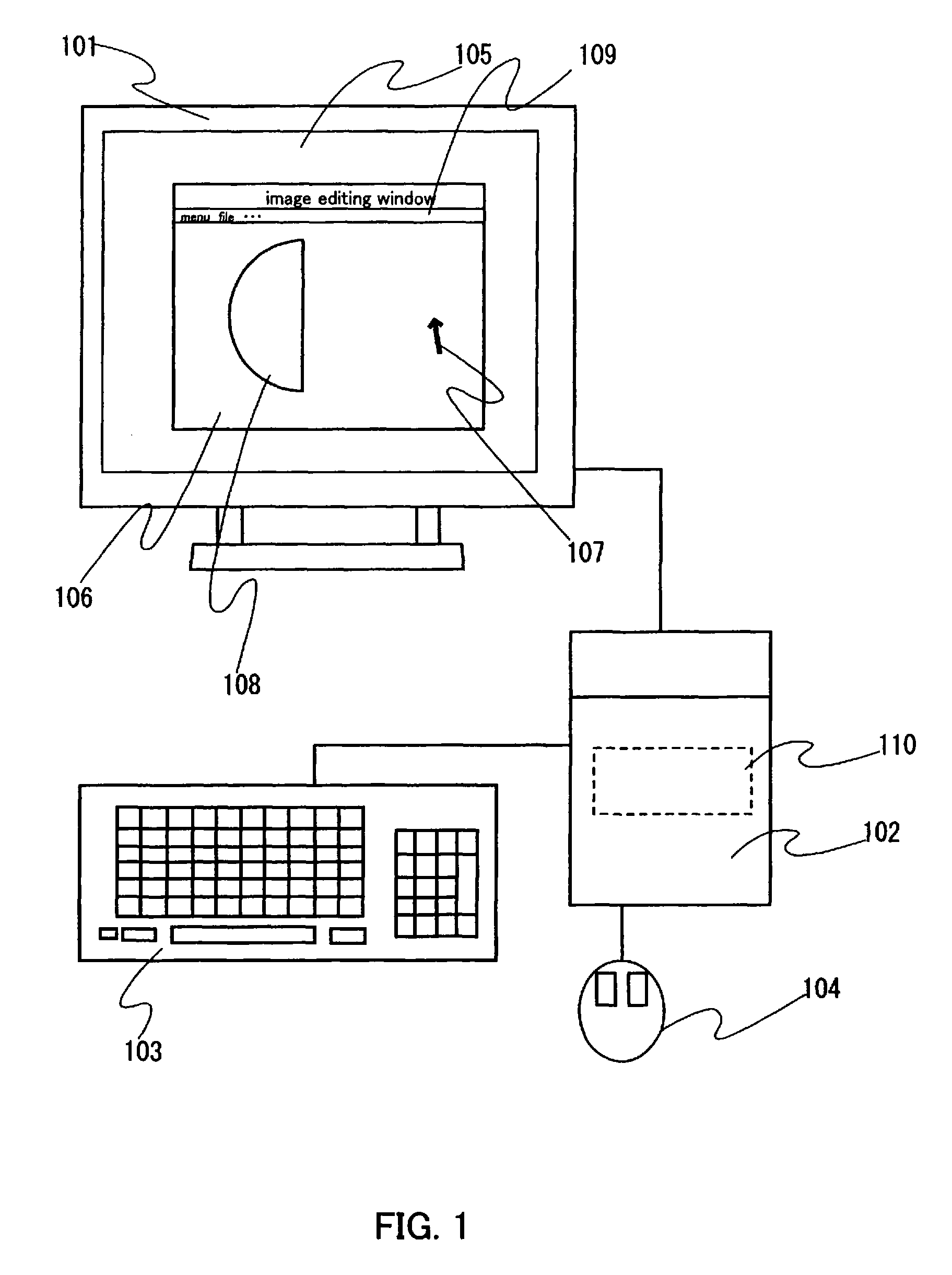
[0040] An embodiment mode of the present invention will be described in detail. FIG. 1 is a view showing a pattern diagram of computer peripheral equipment and an operation screen.
[0041]FIG. 1 shows a display housing 101, a computer 102, a keyboard 103, and a mouse 104. The computer 102 is connected to the display housing 101, the mouse 104 and the keyboard 103. The display housing 101 includes a display portion 105, in which an image editing window (also referred to as a work area, an editing screen, or a window) 106, a mouse cursor 107 (also simply referred to as a cursor), a two dimensional figure (referred to as an image or an object) 108, and a toolbar 109 are displayed. Also, a memory portion 110 for storing image information or the like is included inside the computer 102.
[0042]FIGS. 2A to 2F sequentially describe a method for synthesizing an image in the image editing window 106 of the display portion 105 in FIG. 1. FIGS. 2A to 2F show an image editing window 201, a mouse ...
embodiment mode 2
[0063] Another embodiment mode of the present invention will be described in detail. As for an image editing method of the present invention, a method, by which efficiency in an image editing is increased by iconifying an image which is divided by processing an image which is already displayed and saving to read the image at the time of editing the image again, will be described in detail.
[0064] Computer peripheral equipment outside an image editing window and an operation screen in an image editing method in this embodiment mode are similar to FIG. 1; therefore, the description thereof is omitted here. If necessary in this embodiment mode, the description of FIG. 1 is used.
[0065]FIGS. 7A to 7F subsequently describe a method for dividing an image to be iconified in an image editing window 106 of a display portion 105 in FIG. 1. FIGS. 7A to 7F show an image editing window 701; a mouse cursor 702; a two dimensional figure (object) 703; and a toolbar 704.
[0066] Hereinafter, an image...
PUM
 Abstract
Description
Claims
Application Information