

Print head apparatus with malfunction detector
- Summary
- Abstract
- Description
- Claims
- Application Information
AI Technical Summary
Benefits of technology
Problems solved by technology
Method used
Image

Examples
Embodiment Construction
taken together with the drawings.
BRIEF DESCRIPTION OF THE DRAWINGS
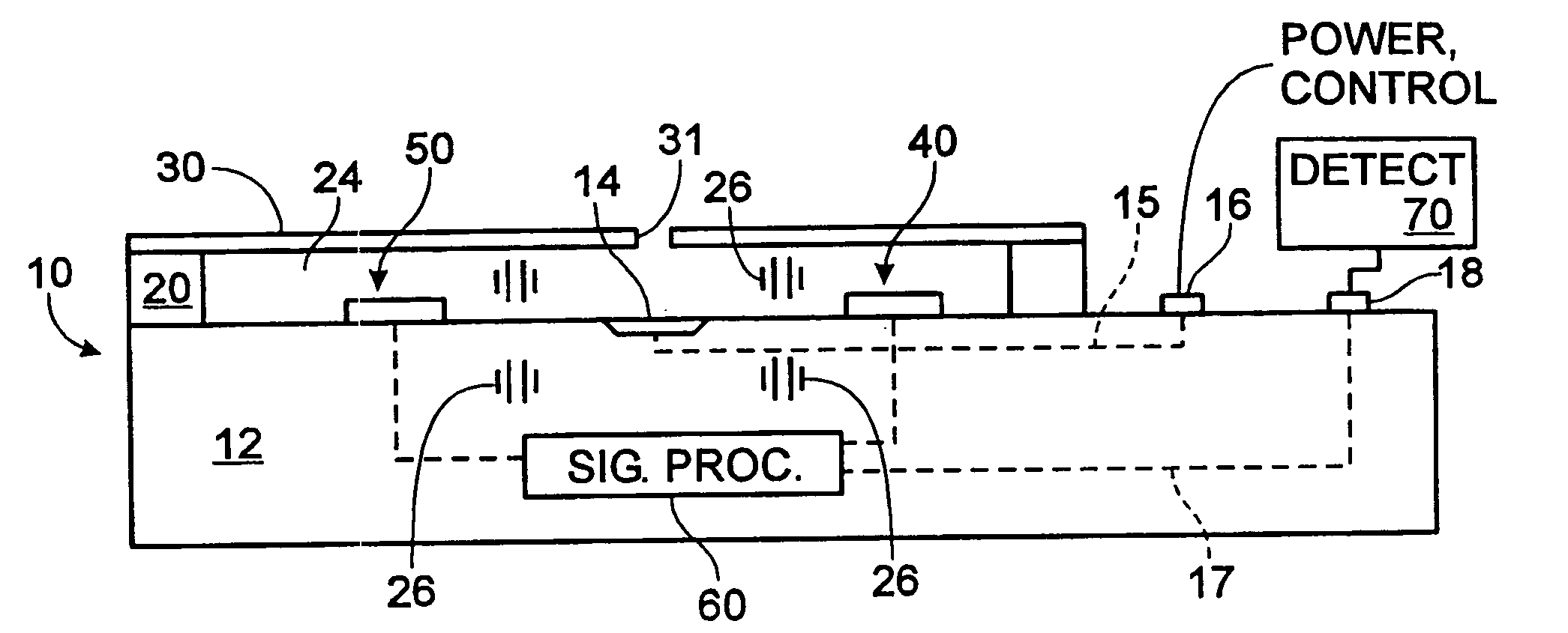
[0010]FIG. 1 is a cross sectional side view of a print head in accordance with the present invention.
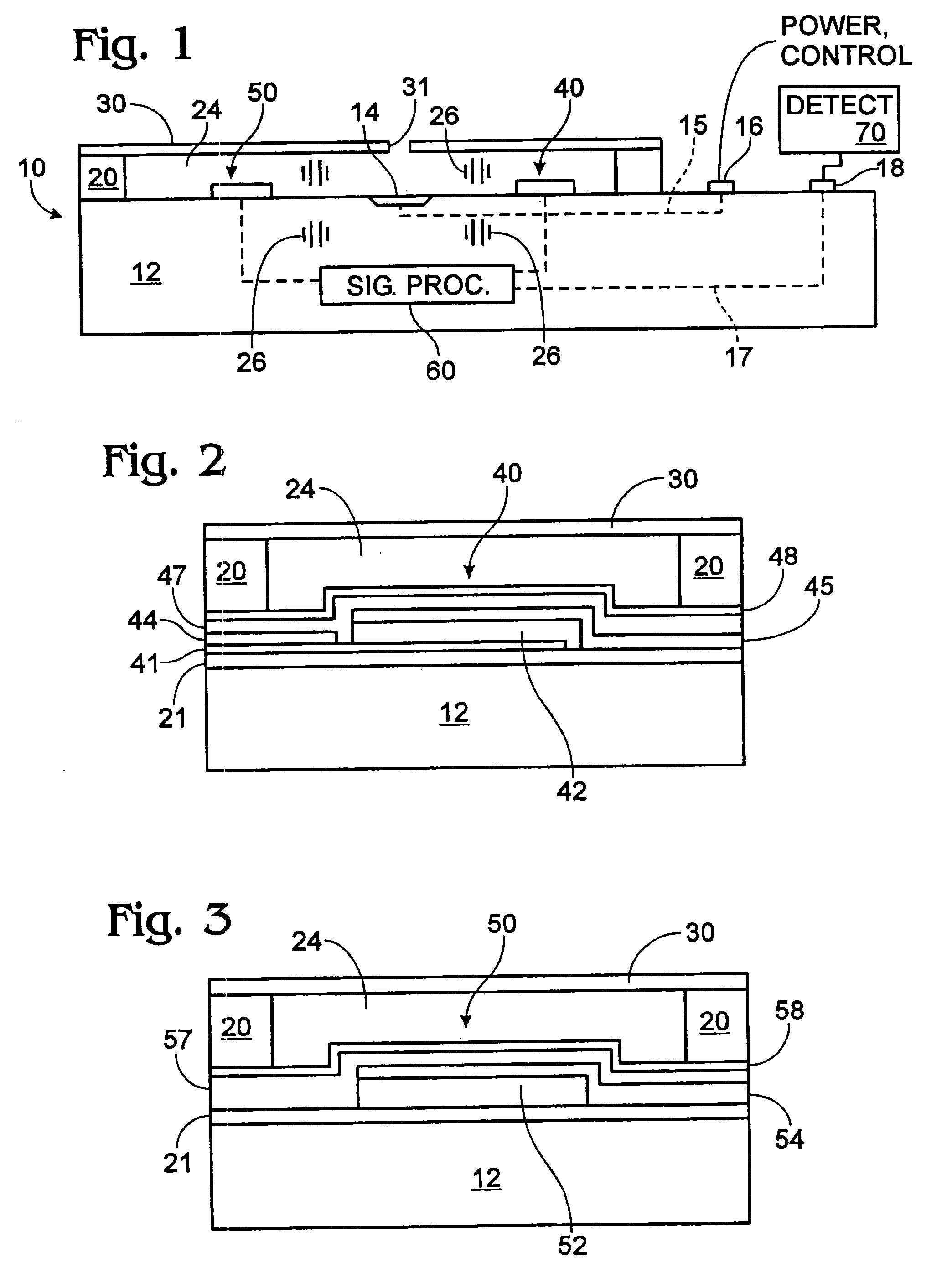
[0011]FIG. 2 is a side view of a piezoelectric acoustic wave transducer in accordance with the present invention.
[0012]FIG. 3 is a side view of a portion of an interdigitated pressure wave transducer in accordance with the present invention.
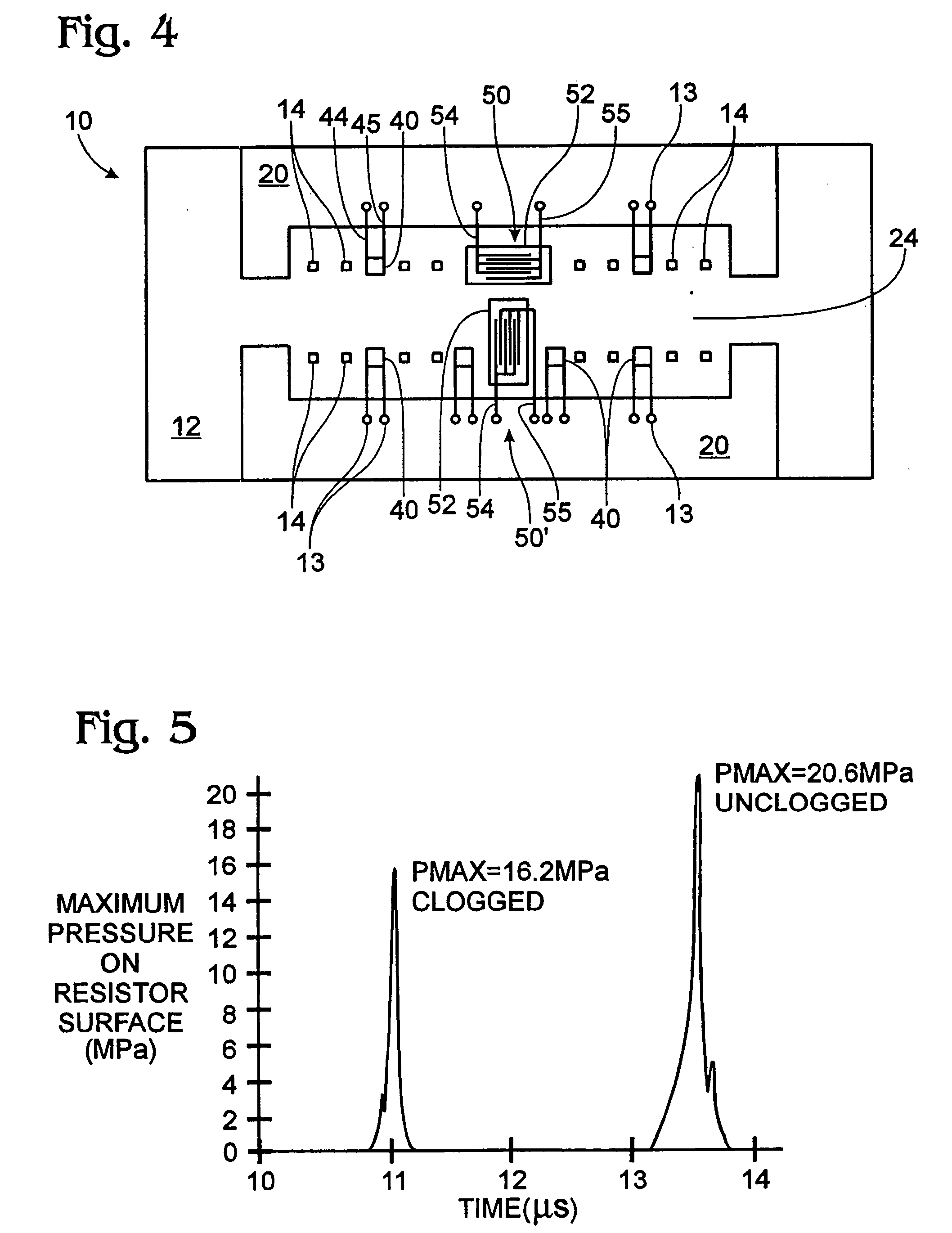
[0013]FIG. 4 is a plan view of an arrangement of piezoelectric acoustic pressure wave transducers and interdigitated piezoelectric pressure wave transducers in a print head in accordance with the present invention.
[0014]FIG. 5 is a graph of illustrating the pressure on an expulsion mechanism surface versus time for a clogged nozzle firing and an unclogged nozzle firing is shown.
DETAILED DESCRIPTION
[0015] Referring to FIG. 1, a cross sectional side view of a print head 10 in accordance with the present invention is shown. Print head 10 includes a substrate in or on which is pro...
PUM
 Abstract
Description
Claims
Application Information