Control-motor system

a control motor and control motor technology, applied in the direction of electronic commutators, lighting and heating apparatus, instruments, etc., can solve the problems of remarkably difficult malfunction determination in a steering-locked state, and achieve the effect of secure steering control system

Active Publication Date: 2008-02-26
MITSUBISHI ELECTRIC CORP
View PDF20 Cites 6 Cited by
  • Summary
  • Abstract
  • Description
  • Claims
  • Application Information

AI Technical Summary

Benefits of technology

[0009]An objective of the present invention, which has been made to solve the foregoing problems, is to detect a resolver malfunction without fail using a system, for controlling a motor, in which a low-cost resolver having the small number of the poles and a multi-pole motor having advantage in small sizing and high-power outputting are combined.
[0020]A period in which an output-torque direction of a motor is made to be reversed against a pointed one can be made the shortest, and wrong determination due to noises, etc. can be also prevented, so that a resolver-malfunction can be detected without fail, because in a control-motor system according to the present invention, driving the motor is stopped in response to determination in that a malfunction has occurred in the resolver, when the value of the sum continuously stays at not greater than the determination threshold value for a first predetermined time, meanwhile, driving the motor is started in response to determination in that the resolver is in normal operation, when the value of the sum continuously stays at not smaller than the determination threshold value for a second predetermined time.
[0021]A period in which an output-torque direction of a motor is made to be reversed against a pointed one can be made the shortest, and wrong determination due to noises, etc. can be also prevented, so that a resolver-malfunction can be detected without fail, because in a control-motor system according to the present invention, the motor-driving is held in a stop, when the value of the sum continuously stays at not greater than the determination threshold value for a third predetermined time, until the motor is restored, and the first predetermined time is set shorter than the third predetermined time.
[0024]Moreover, excitation-circuit burning when a malfunction has occurred can prevented, because in a control-motor system according to the present invention, the excitation signal is stopped when it is determined that the malfunction has occurred in the resolver.
[0025]Furthermore, a more secure steering control system can be created, because in a control-motor system according to the present invention, an output torque of the motor is made to be transmitted into a steering system of a vehicle.

Problems solved by technology

Depending on a set value of the threshold voltage for determining the malfunction, it has been a problem that the malfunction determination in a steering-locked state may become remarkably difficult.

Method used


Image

  • Control-motor system
  • Control-motor system
  • Control-motor system

Examples


embodiment 1

[0033]A first embodiment according to the present invention is explained with reference to drawings.

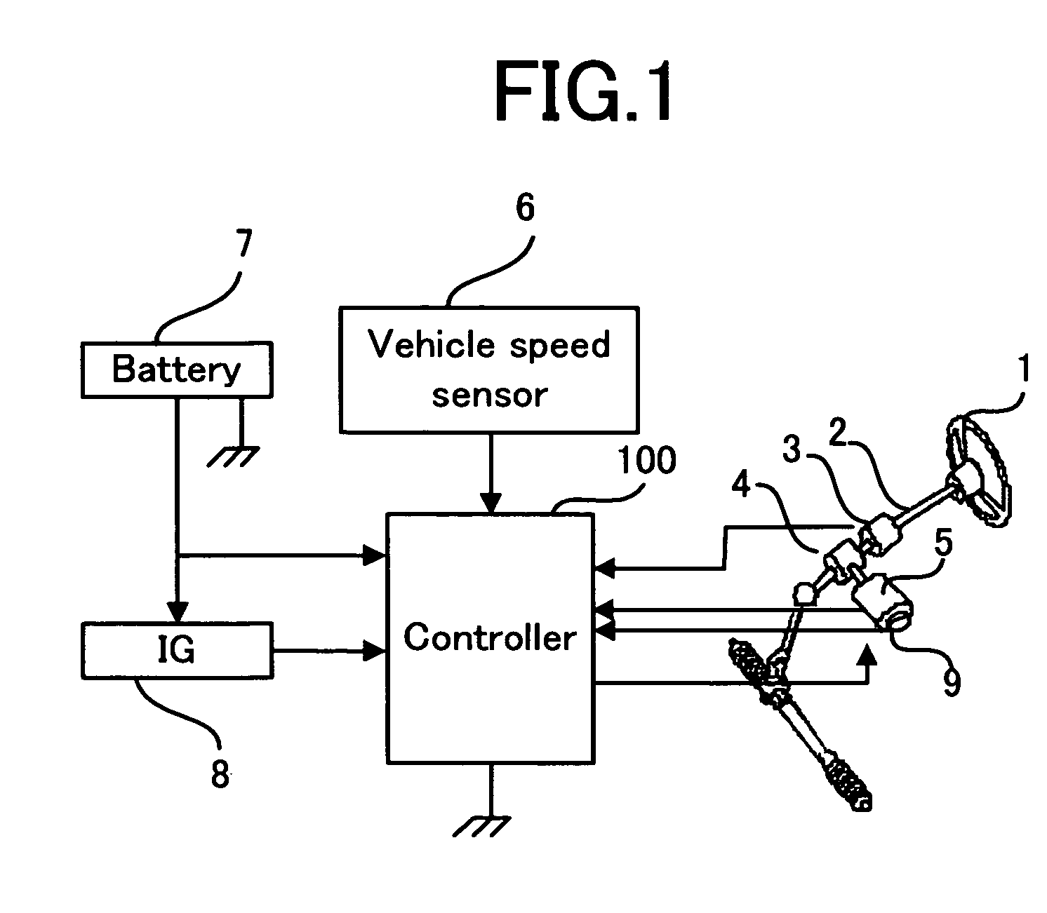
[0034]FIG. 1 is a block diagram illustrating an electromotive-power-steering control system according to the embodiment of the present invention.

[0035]A permanent magnet synchronous motor (hereinafter referred to as a PM motor) 5 that generates a steering assist torque is connected to an end of a steering shaft 2 through a speed reduction gear 4, and a steering wheel 1 is connected to the other end of the steering shaft 2. Moreover, a torque sensor 3 that detects a steering torque of the steering wheel 1 is connected to the steering shaft 2.

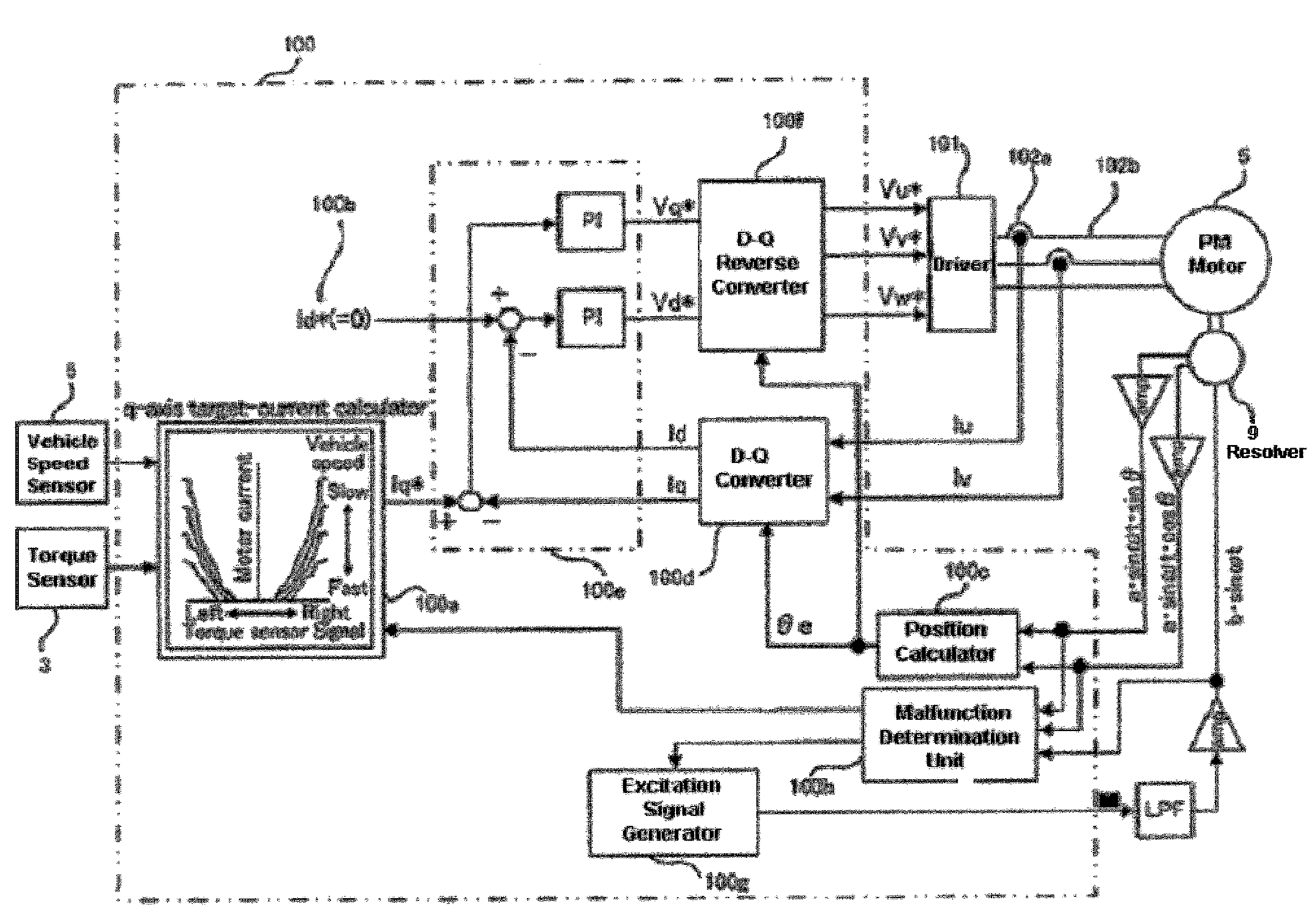
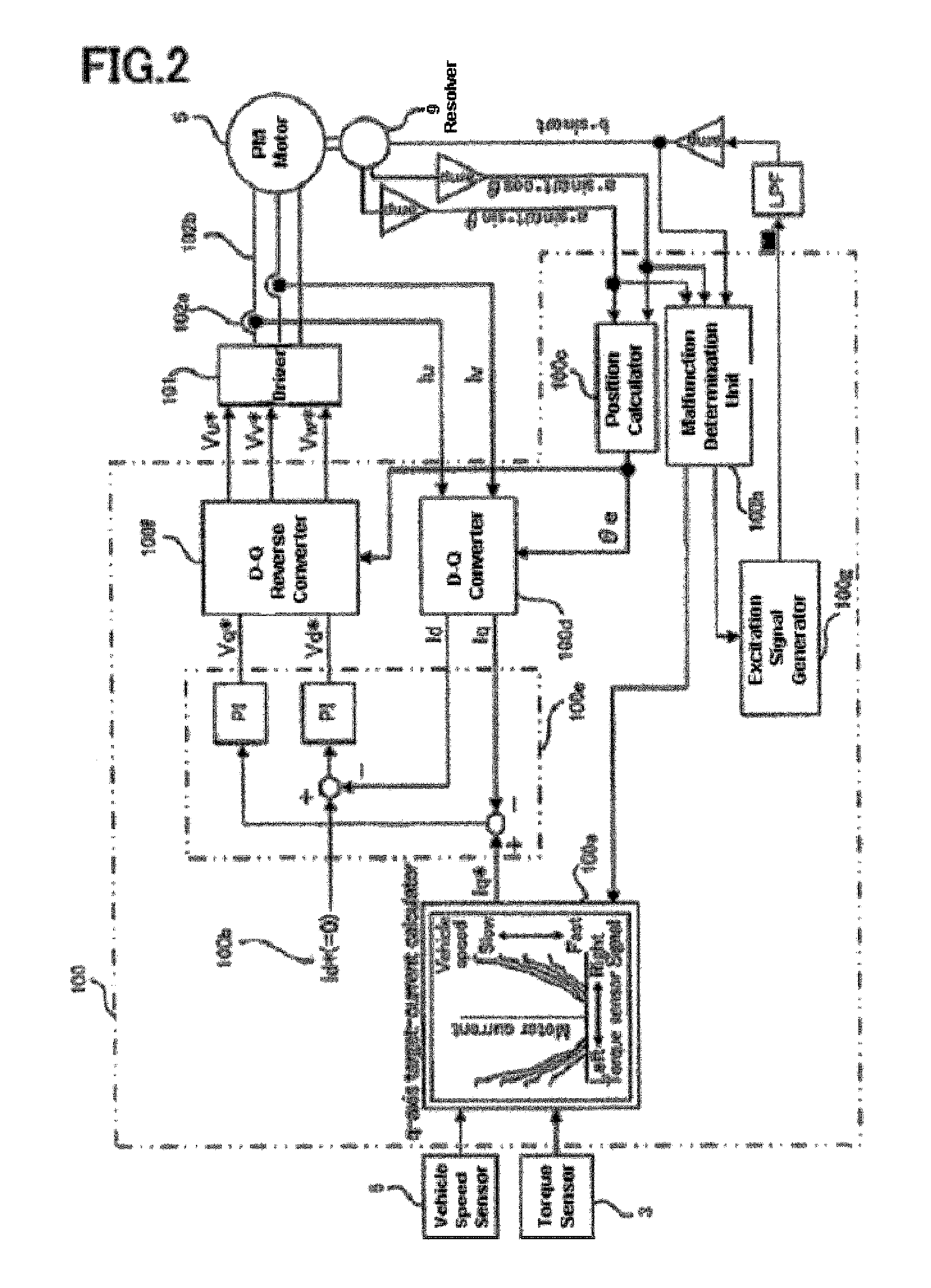
[0036]A controller 100 determines the steering assist torque based on a detected torque value by the torque sensor 3 and a detected vehicle speed value by a vehicle speed sensor 6, and assists the steering operation of the steering wheel 1 by driving the PM motor in response to a rotor position detected by a resolver 9. The controller 100 is also c...

embodiment 2

[0061]FIG. 6 is a configurational view illustrating an electromotive-power-steering control system according to Embodiment 2 of the present invention. Here, elements having the function similar to that in Embodiment 1 are represented by the same numerals, and the explanation is omitted.

[0062]A malfunction-determination unit 100i memorizes a malfunction-determination threshold value calculated in advance based on a resolver-excitation amplitude and transforming rate, thereby it performs malfunction determination based on this memorized malfunction-determination value.

[0063]This embodiment, compared to Embodiment 1, has an advantage in that a resolver-excitation-signal monitor circuit need not be provided, and calculation of the malfunction-determination threshold value is not required.


PUM


Abstract

An objective is to detect a resolver malfunction without fail, using a low-cost resolver having the small number of the poles, and a control-motor system having advantage in small sizing and high-power outputting. In the control-motor system, the system for driving a 2m-pole motor based on a rotor rotation angle θ detected by a 2n-pole resolver, where m and n being counting numbers, is characterized in that: the sum of the square of a signal modulated by sin θ and the square of a signal modulated by cos θ in the resolver in which an excitation signal generated in said system is modulated by sin θ and cos θ in response to the rotor rotation angle θ of the resolver is compared to a predetermined malfunction threshold value, so that malfunction determination related to the resolver is performed, and also, given that the sum is a2 when the resolver is recognized to be in normal operation, the malfunction determination threshold value is made to be not smaller than {a×cos((π / 2) / (m / n))}2.

Description

BACKGROUND[0001]1. Field of the Invention[0002]The present invention relates to resolver-malfunction-detection methods that are most suitable for electromotive power steering systems for vehicles, etc., and to systems for controlling motors using the methods.[0003]2. Description of the Related Art[0004]FIG. 7 is a view illustrating a conventional resolver-signal-detection system (refer to Japanese Laid-Open Utility Model Publication 99,815 / 1987).[0005]In FIG. 7, numerals 51a and 51b denote square circuits, numerals 52a and 52b denote rectifier circuits, numeral 53 denotes an adder circuit, numeral 54 denotes a voltage regulator circuit, and numeral 55 denotes a comparator circuit.[0006]A method is disclosed, in which, by comparing the sum of the square of a sine signal and the square of a cosine signal with a predetermined voltage, so that an abnormality is determined.SUMMARY OF THE INVENTION[0007]In the conventional resolver-signal-detection system, the publication has not disclose...

Claims


Application Information

Patent Timeline
Patent Type & Authority Patents(United States)
IPC IPC(8): H02H7/08B62D5/04B62D6/00B62D119/00G01D5/245H02P6/06H02P6/08H02P6/12H02P6/16H02P6/28
CPCB62D5/0487B62D5/049Y02T10/7258G01D3/08Y02T10/72
Inventor MATSUSHITA, MASAKIKIFUKU, TAKAYUKIDOI, HIDEKIOHMAE, KATSUHIKO
Owner MITSUBISHI ELECTRIC CORP
Why Eureka
Try Eureka