Image quality adjustment method and system

a technology of image quality and adjustment method, applied in the field of image quality adjustment method and system, can solve the problems of adding system cost, substantial physical space requirement, and set points stored in tables that can become outdated or inappropriate,

Inactive Publication Date: 2006-11-02
XEROX CORP
View PDF65 Cites 75 Cited by
  • Summary
  • Abstract
  • Description
  • Claims
  • Application Information

AI Technical Summary

Problems solved by technology

However, many factors, including temperature, humidity, ink or toner age, and / or component wear, tend to move the output of a rendering or printing system away from the ideal or target output.
While these methods may be effective in stabilizing and / or controlling engine response curves, they employ sensors and associated controls that add cost to the systems and may have substantial physical space requirements.
However, over time, due to system wear and other sources of drift, the set points stored in the tables can become outdated or inappropriate.
While an observer might not ever notice the subtle variations when reviewing the output of either engine alone, when their output is compiled and displayed in the facing pages of a booklet the variation may become noticeable and be perceived by a printing services' customer as an issue of quality.
These patents, however, are not concerned with systems and methods for improving or achieving image consistency between or among a plurality of marking engines.

Method used


Image

  • Image quality adjustment method and system
  • Image quality adjustment method and system
  • Image quality adjustment method and system

Examples


Embodiment Construction

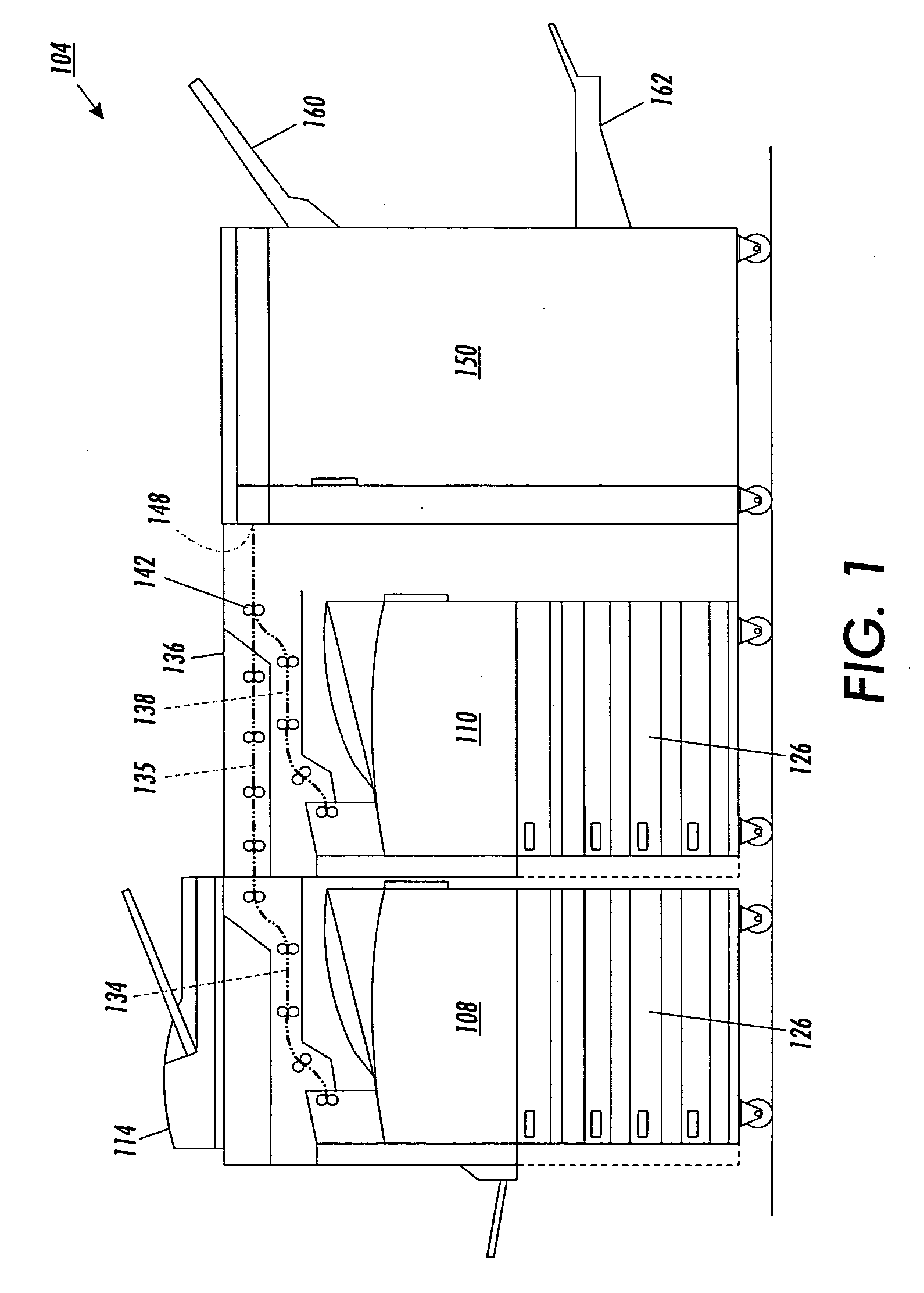
[0062]FIG. 1 illustrates a first image (or document) rendering (or processing) system 104 suitable for incorporating embodiments of the methods and systems disclosed herein. The first image rendering system 104 includes a first image output terminal (IOT) 108, a second image output terminal 110 and an image input device 114, such as a scanner, imaging camera or other device. Each image output terminal 108, 110 includes a plurality of input media trays 126 and an integrated marking engine (e.g., see FIG. 2 and related description below). The first IOT 108 may support the image input device 114 and includes a first portion 134 of a first output path. A second portion 135 of the first output path is provided by a bypass module 136. The second IOT 110 includes a first portion 138 of a second output path. A third portion of the first path and a second portion of the second path begin at a final nip 142 of the second IOT 110 and include an input to a finisher 150.

[0063] The finisher 150 ...


PUM


Abstract

An image rendering system periodically prints test patches on a duplex sheet from a plurality of marking engines, using a simple emitter-detector pair as a feedback means in image quality control. Image lightness is controlled by analyzing the test patches to determine updated marking engine actuator set points. For instance, ROS exposure and / or scorotron grid voltages are adjusted to maintain image lightness consistency between marking engines.

Description

CROSS-REFERENCE TO RELATED APPLICATIONS [0001] The following applications, the disclosures of each being totally incorporated herein by reference are mentioned: [0002] U.S. Provisional Application Ser. No. 60 / 631,651 (Attorney Docket No. 20031830-US-PSP), filed Nov. 30, 2004, entitled “TIGHTLY INTEGRATED PARALLEL PRINTING ARCHITECTURE MAKING USE OF COMBINED COLOR AND MONOCHROME ENGINES,” by David G. Anderson, et al.; [0003] U.S. Provisional Patent Application Ser. No. 60 / 631,918 (Attorney Docket No. 20031867-US-PSP), filed Nov. 30, 2004, entitled “PRINTING SYSTEM WITH MULTIPLE OPERATIONS FOR FINAL APPEARANCE AND PERMANENCE,” by David G. Anderson et al.; [0004] U.S. Patent Provisional Patent Application Ser. No. 60 / 631,921 (Attorney Docket No. 20031867Q-US-PSP), filed Nov. 30, 2004, entitled “PRINTING SYSTEM WITH MULTIPLE OPERATIONS FOR FINAL APPEARANCE AND PERMANENCE,” by David G. Anderson et al.; [0005] U.S. patent application Ser. No. 10 / 761,522 (Attorney Docket A2423-US-NP), file...

Claims


Application Information

Patent Timeline
Patent Type & Authority Applications(United States)
IPC IPC(8): G06K9/40
CPCB41J29/393G03G2215/00042G03G15/5062G03G2215/00586G03G2221/1696G03G2215/00067
Inventor GRACE, ROBERT E.
Owner XEROX CORP
Why Eureka
Try Eureka