Optical recording medium, and recording and reproducing method

Inactive Publication Date: 2006-11-02
RICOH KK
View PDF8 Cites 4 Cited by
  • Summary
  • Abstract
  • Description
  • Claims
  • Application Information

AI Technical Summary

Benefits of technology

[0009] The recording method of the present invention is characterized in that the optical recording medium of the present invention is irradiated with a laser beam from the light absorbing and heat generating part side, and the power level of the laser beam is increased by use of the period of recording parts in the track direction to thereby record information.
[0010] A first aspect of the recording and reproducing method of the present invention is characterized in that the optical recording medium of the present invention is irradiated with a laser beam from the light absorbing and heat generating part side, the power level of the laser beam is increased by use of the period of recording parts in the track direction to thereby re

Problems solved by technology

However, it is extremely difficult to completely prevent cross-write and cross-erase events even with any of the optical disc structures in the prior art, and it is impossible to drastically reduce the track p

Method used


Image

  • Optical recording medium, and recording and reproducing method
  • Optical recording medium, and recording and reproducing method
  • Optical recording medium, and recording and reproducing method

Examples


Example

Example 1 and Comparative Example 1

Preparation of Linear-Shaped Recording Part

[0147]FIGS. 8A to 8C respectively show a method for producing recording parts of an optical recording medium of the present invention, which are produced in accordance with the following examples.

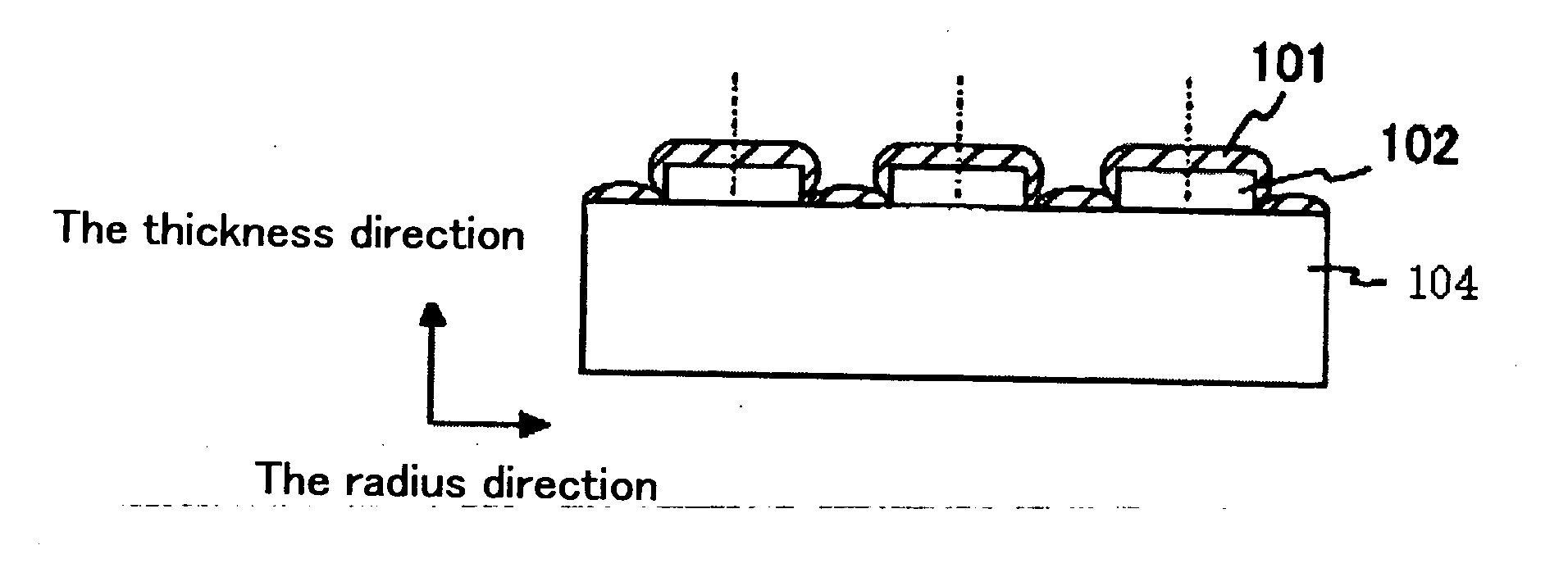
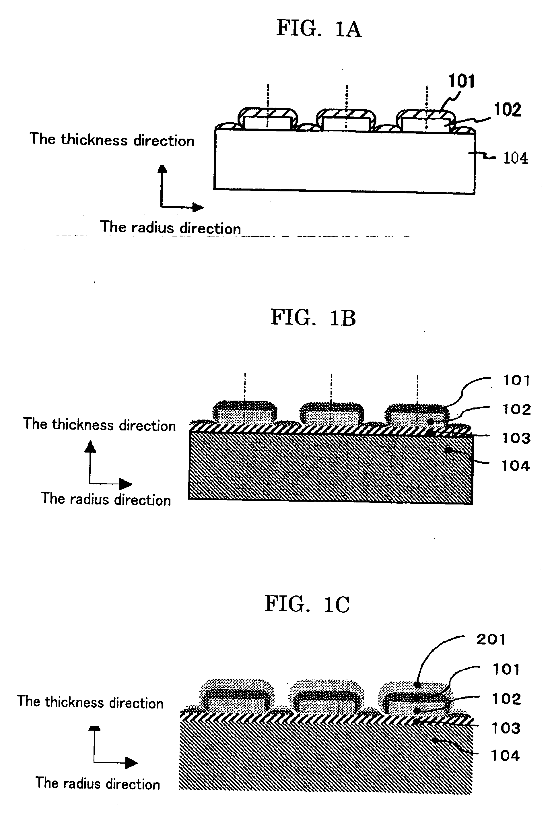
[0148]FIG. 8A is a view showing a structure of an optical recording medium before the recording parts were processed in a linear form. The recording part 102 was made of ZnS—SiO2. For the composition ratio of the material, the material contained ZnS at 80 mole % and SiO2 at 20 mole %. The thickness of the recording parts 102 was 45 nm.

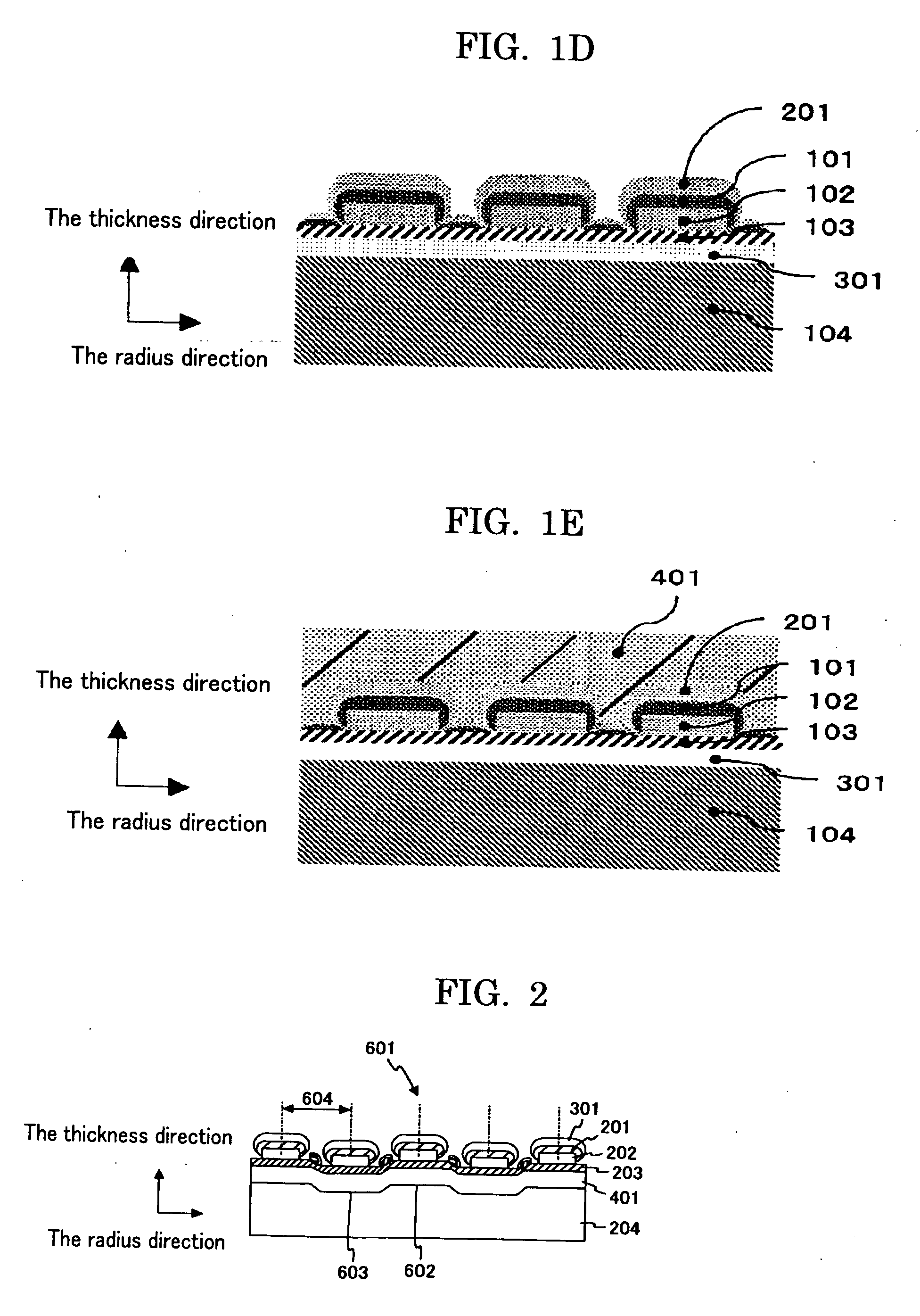
[0149] Light absorbing and heat generating part 103 was made of Ge, and the thickness thereof was 10 nm. Thermal conduction-suppressing layer 301 was made of ZnS—SiO2. For the composition ratio of the material, the material contained ZnS at 80 mole % and SiO2 at 20 mole %. The thickness of the thermal conduction-suppressing layer 301 was 50 nm.

[0150] Substrate 104 was made of po...

Example

[0157]FIG. 11 shows a structure of an optical recording medium produced in Comparative Example 1.

[0158] The reference numeral 1301 represents a recording part. The recording part was made of ZnS—SiO2—Ag. For the composition ratio of the material, the material contained ZnS at 70 mole %, SiO2 at 20 mole %, and Ag at 10 mole %. The thickness of the recording part 1301 was 45 nm.

[0159] The reference numeral 1302 represents a light absorbing and heat generating part. The light absorbing and heat generating part was made of AgInSbTe. For the composition ratio of the material, the material contained Ag at 4 atomic %, In at 7 atomic %, Sb at 61 atomic %, and Te at 28 atomic %. The thickness of the light absorbing and heat generating part 1302 was 20 nm.

[0160] The reference numeral 1303 represents a recording part. The recording part was made of ZnS—SiO2. For the composition ratio of the material, the material contained ZnS at 80 mole % and SiO2 at 20 mole %. The thickness of the recordi...

Example

[0162] The optical recording medium of Comparative Example 1 in which plural thin layers were formed in a laminar structure was compared to the optical recording medium of Example 1 shown in FIG. 10 by recording information on the respective optical recording media. The wavelength of the laser beam used in the recording was 405 nm, and the numerical aperture of the object lens was 0.85. FIG. 12 shows the comparison results. In FIG. 12, the reference numeral 1401 shown on the right side of the view represents a recording pulse. The laser power was modulated between the recording power level and the bias power level to record information. The recording period was 400 nm. The recording and reproducing linear velocity was 3.5 m / sec. The reproducing power was 0.2 mW. In FIG. 12, the reference numeral 1402 shown on the left side of the view represents changes in signal amplitude with respect to each recording power. The reference numeral 1403 represents recording results of the optical re...


PUM


Abstract

An optical recording medium is provided with at least a substrate, light absorbing and heat generating parts each of which absorbs light and generates heat, and recording parts, and each of the recording parts are formed between two recording tracks.

Description

BACKGROUND OF THE INVENTION [0001] 1. Field of the Invention [0002] The present invention relates to a recordable optical recording medium for use in recording information by means of laser beam irradiation and specifically relates to a recordable optical recording medium, which may be hereinafter referred to as “optical disc”, capable of reducing the track pitch width to thereby obtain high-density recording, and the present invention also relates to a recording and reproducing method using the optical recording medium. [0003] 2. Description of the Related Art [0004] It has been known that a margin is provided to track pitch of a recordable optical disc in order to prevent cross-write, cross-erase, and cross-talk events, which are caused from thermal interference between adjacent tracks. For example, when the wavelength of a laser beam for use is 405 nm, and the numerical aperture NA of an object lens of the optical system is 0.85, the track pitch of the optical disc is typically s...

Claims


Application Information

Patent Timeline
IPC IPC(8): G11B7/24G11B7/243
CPCG11B7/24G11B7/2433G11B7/2437G11B7/252G11B2007/24324G11B2007/24308G11B2007/24312G11B2007/2432G11B2007/24304
Inventor MIURA, HIROSHI
Owner RICOH KK
Why Eureka
Try Eureka