Dynamic adjustment of power plant output based on electrical grid characteristics

Active Publication Date: 2012-06-07
VESTAS WIND SYST AS
View PDF7 Cites 55 Cited by
  • Summary
  • Abstract
  • Description
  • Claims
  • Application Information

AI Technical Summary

Benefits of technology

[0010]In another embodiment of the invention, a computer-implemented method is provided for controlling the power output by a power plant to a power grid. The power plant is of the type that includes a wind farm that outputs a wind farm power signal and a grid power converter that receives the wind farm power signal and outputs a power signal for the power grid. The method comprises, in response to a measured frequency of the power gri

Problems solved by technology

Due to the natural intermittency of wind as well as outages that occur when a transmission line from a wind turbine or the wind turbine itself fails, the power output from a particular wind turbine or wind farm is less consistent than the power output from conventional fossil fuel-fired power plants.
As a result, the power from wind turbines operating at nominal conditions in a wind farm may not meet output requirements for the power grid, resulting in decreasing frequency of the power grid.
For example, the power from the wind power plant often will not track the forecasted power due to wind forecast, transmission line, or wind turbine errors.
As another example, the rate of change of power for a wind power plant may be outside of a desired range because of wind gusts.
As a result, the power from wind turbines may not meet output requirements for the power grid.
For example, a load may be added to the power grid and result in decreasing frequency of the power grid.
On the other hand, a sudden withdrawal of a load may result in increasing frequency of the power grid.
In the curtailed mode, the wind turbines are not generating all the

Method used


Image

  • Dynamic adjustment of power plant output based on electrical grid characteristics
  • Dynamic adjustment of power plant output based on electrical grid characteristics
  • Dynamic adjustment of power plant output based on electrical grid characteristics

Examples


Example

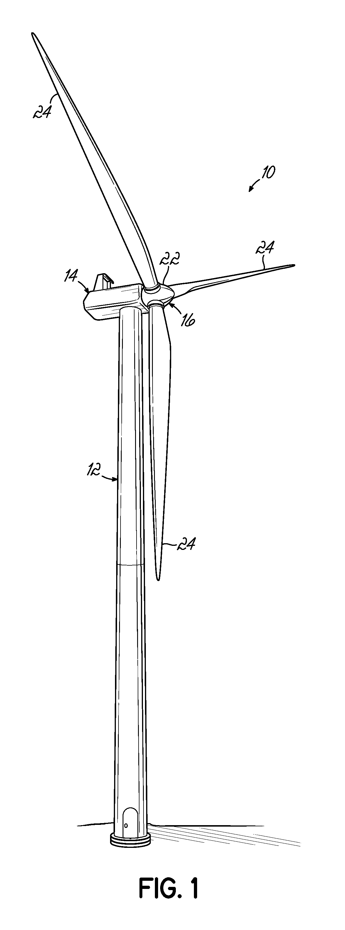
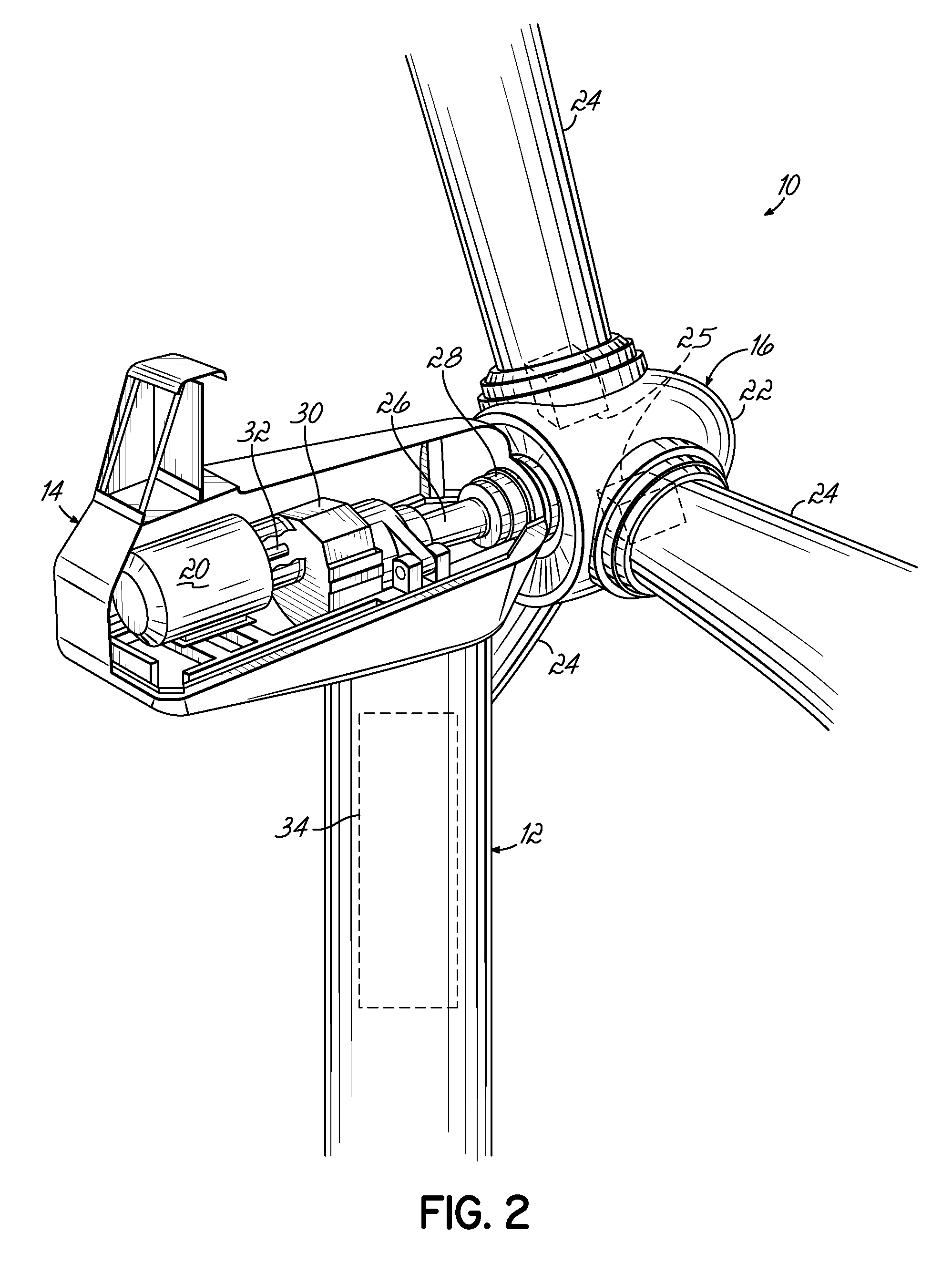
[0022]With reference to FIGS. 1 and 2 and in accordance with an embodiment of the invention, a wind turbine 10, which is depicted as a horizontal-axis machine, includes a tower 12, a nacelle 14 disposed at the apex of the tower 12, and a rotor 16 operatively coupled to a generator 20 housed inside the nacelle 14. In addition to the generator 20, the nacelle 14 houses miscellaneous components required for converting wind energy into electrical energy and various components needed to operate, control, and optimize the performance of the wind turbine 10. The tower 12 supports the load presented by the nacelle 14, the rotor 16, and other components of the wind turbine 10 that are housed inside the nacelle 14 on an underlying foundation. The tower 12 of the wind turbine 10 also operates to elevate the nacelle 14 and rotor 16 to a height above ground level or sea level, as may be the case, at which faster moving air currents of lower turbulence are typically found.

[0023]The rotor 16 inclu...


PUM


Abstract

Method, power plant, and computer program product for use in controlling power output by a power plant. The power plant includes a wind farm with a plurality of wind turbines, a grid power converter (such as one or more HVDC links), a sensor to measure the frequency of a power grid, and a supervisory controller. The supervisory controller implements a control algorithm that adjusts the power output from the power plant in response to the frequency of the power grid dropping below a first target frequency by changing the pitch of the blades of at least one wind turbine, increasing the level of a portion of the power contributed by at least one wind turbine, or increasing the level of the power output by the grid power converter.

Description

BACKGROUND[0001]This application relates generally to electrical power generation and, more specifically, to methods, systems, and computer program products for use in adjusting the power output therefrom.[0002]A wind farm, or wind park, includes a group of wind turbines that operate collectively as a power plant that generates a power output to a power grid. Wind turbines can be used to produce electrical energy without the necessity of fossil fuels. Generally, a wind turbine is a rotating machine that converts the kinetic energy of the wind into mechanical energy and the mechanical energy subsequently into electrical power. Conventional horizontal-axis wind turbines include a tower, a nacelle located at the apex of the tower, and a rotor that is supported in the nacelle by a shaft. A generator, which is housed inside the nacelle, is coupled by the shaft with the rotor. Wind currents activate the rotor, which transfers torque to the generator. The generator produces electrical powe...

Claims


Application Information

Patent Timeline
IPC IPC(8): H02P9/04
CPCF03D7/0224Y02E40/72F03D7/048F03D9/005F03D9/02F05B2270/337H02J3/32H02J3/386H02J3/46H02J13/0062H02J13/0075H02J13/0079Y02E10/723Y02B90/222Y02E70/30Y02E10/763Y02E10/766Y04S10/123Y04S10/14Y04S20/12Y02B90/2653Y02B90/2638Y04S40/124Y04S40/126Y02E60/722Y02E60/7838Y02E60/7853F03D7/0284F03D9/10F03D9/257F03D80/88F03D15/10F03D9/11H02J2300/28H02J3/381H02J13/00016H02J13/00028Y02B90/20Y02E10/72Y02E10/76Y02E40/70Y02E60/00H02J13/00022
Inventor HAJ-MAHARSI, MOHAMEDSINGH, SUNITASOBRINK, KENT HANS
Owner VESTAS WIND SYST AS
Why Eureka
Try Eureka